STC进阶开发(二)独立按键、数码管
前言
? ? ? ? 上一期我们介绍了PWM、ADC以及热敏电阻,这一期我们学习一下开发板上的独立按键以及介绍一下晶体管。话不多说,开整!
独立按键
原理图
需求
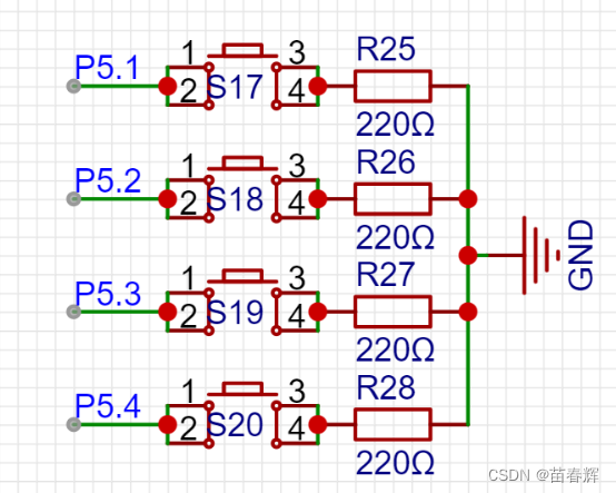
? ? ? ? 我们要通过串口获取每个按键是按下还是弹起,通过原理图我们可以知道,但开关被按下时,P51P52P53P54的引脚的电压就为低电压,因为右边是接地,断开状态是高电压。下面这些代码就是去获取按键状态。
代码展示
获取单个按键状态
#include "GPIO.h"
#include "NVIC.h"
#include "Delay.h"
#include "UART.h"
#include "Switch.h"

#define KEY1 P51
#define KEY2 P52
#define KEY3 P53
#define KEY4 P54

//1. IO模式配置

void GPIO_config(void) {
	GPIO_InitTypeDef	GPIO_InitStructure;		//结构定义
	GPIO_InitStructure.Pin  = GPIO_Pin_1 | GPIO_Pin_2 | GPIO_Pin_3 | GPIO_Pin_4;		//指定要初始化的IO,
	GPIO_InitStructure.Mode = GPIO_PullUp;	//指定IO的输入或输出方式,GPIO_PullUp,GPIO_HighZ,GPIO_OUT_OD,GPIO_OUT_PP
	GPIO_Inilize(GPIO_P5, &GPIO_InitStructure);//初始化
}

//2. 串口配置
void UART_config(void) {
	// >>> 记得添加 NVIC.c, UART.c, UART_Isr.c <<<
    COMx_InitDefine		COMx_InitStructure;					//结构定义
    COMx_InitStructure.UART_Mode      = UART_8bit_BRTx;	//模式, UART_ShiftRight,UART_8bit_BRTx,UART_9bit,UART_9bit_BRTx
    COMx_InitStructure.UART_BRT_Use   = BRT_Timer1;			//选择波特率发生器, BRT_Timer1, BRT_Timer2 (注意: 串口2固定使用BRT_Timer2)
    COMx_InitStructure.UART_BaudRate  = 115200ul;			//波特率, 一般 110 ~ 115200
    COMx_InitStructure.UART_RxEnable  = ENABLE;				//接收允许,   ENABLE或DISABLE
    COMx_InitStructure.BaudRateDouble = DISABLE;			//波特率加倍, ENABLE或DISABLE
    UART_Configuration(UART1, &COMx_InitStructure);		//初始化串口1 UART1,UART2,UART3,UART4

  	NVIC_UART1_Init(ENABLE,Priority_1);		//中断使能, ENABLE/DISABLE; 优先级(低到高) Priority_0,Priority_1,Priority_2,Priority_3
    UART1_SW(UART1_SW_P30_P31);		// 引脚选择, UART1_SW_P30_P31,UART1_SW_P36_P37,UART1_SW_P16_P17,UART1_SW_P43_P44
}

void main(){

	//0. EA中断
	EA = 1 ;

	//1. 配置IO
	GPIO_config();

	//2. 配置串口
	UART_config();

	printf("start...\n");

	while(1){

		if(KEY1 == 1){ // 表示是弹起状态
			printf("KEY1:: 弹起.\n");
		}else if(KEY1 == 0){ // 表示按下状态
			printf("KEY1:: 按下.\n");
		}


		delay_ms(20);
	}
}
获取单个按键状态(只打印一次)
? ? ? ? 只打印一次我们就要借助中间变量来记录上一次按键状态。
#include "GPIO.h"
#include "NVIC.h"
#include "Delay.h"
#include "UART.h"
#include "Switch.h"

#define KEY1 P51
#define KEY2 P52
#define KEY3 P53
#define KEY4 P54

//1. IO模式配置

void GPIO_config(void) {
	GPIO_InitTypeDef	GPIO_InitStructure;		//结构定义
	GPIO_InitStructure.Pin  = GPIO_Pin_1 | GPIO_Pin_2 | GPIO_Pin_3 | GPIO_Pin_4;		//指定要初始化的IO,
	GPIO_InitStructure.Mode = GPIO_PullUp;	//指定IO的输入或输出方式,GPIO_PullUp,GPIO_HighZ,GPIO_OUT_OD,GPIO_OUT_PP
	GPIO_Inilize(GPIO_P5, &GPIO_InitStructure);//初始化
}

//2. 串口配置
void UART_config(void) {
	// >>> 记得添加 NVIC.c, UART.c, UART_Isr.c <<<
    COMx_InitDefine		COMx_InitStructure;					//结构定义
    COMx_InitStructure.UART_Mode      = UART_8bit_BRTx;	//模式, UART_ShiftRight,UART_8bit_BRTx,UART_9bit,UART_9bit_BRTx
    COMx_InitStructure.UART_BRT_Use   = BRT_Timer1;			//选择波特率发生器, BRT_Timer1, BRT_Timer2 (注意: 串口2固定使用BRT_Timer2)
    COMx_InitStructure.UART_BaudRate  = 115200ul;			//波特率, 一般 110 ~ 115200
    COMx_InitStructure.UART_RxEnable  = ENABLE;				//接收允许,   ENABLE或DISABLE
    COMx_InitStructure.BaudRateDouble = DISABLE;			//波特率加倍, ENABLE或DISABLE
    UART_Configuration(UART1, &COMx_InitStructure);		//初始化串口1 UART1,UART2,UART3,UART4

  	NVIC_UART1_Init(ENABLE,Priority_1);		//中断使能, ENABLE/DISABLE; 优先级(低到高) Priority_0,Priority_1,Priority_2,Priority_3
    UART1_SW(UART1_SW_P30_P31);		// 引脚选择, UART1_SW_P30_P31,UART1_SW_P36_P37,UART1_SW_P16_P17,UART1_SW_P43_P44
}

void main(){
//	按下
//	按下
//	按下
//	弹起  // 只需要在状态从按下变到弹起的时候执行一次即可
//	弹起
//	弹起
//	按下  // 只需要在状态从弹起变到按下的时候执行一次即可
//	按下
//	按下
//	弹起  // 只需要在状态从按下变到弹起的时候执行一次即可
//	弹起
//	弹起

		//定义一个中间变量,事先记录着上一次按键的状态
	// 因为按键默认就是弹起的,我们进来只能做按下,所以就相当于是记录按键的上一次状态是弹起
	int key_last_state = 1 ;

	//0. EA中断
	EA = 1 ;

	//1. 配置IO
	GPIO_config();

	//2. 配置串口
	UART_config();

	printf("start...\n");


	while(1){

		if(KEY1 == 1 && key_last_state == 0){ // 表示是弹起状态
			printf("KEY1:: 弹起.\n");

			key_last_state = 1 ;

		}else if(KEY1 == 0 && key_last_state == 1){ // 表示按下状态
			printf("KEY1:: 按下.\n");

			key_last_state = 0;
		}


		delay_ms(20);
	}
}
获取单个按键状态(控制LED灯)
#include "GPIO.h"
#include "NVIC.h"
#include "Delay.h"
#include "UART.h"
#include "Switch.h"

#define KEY1 P51
#define KEY2 P52
#define KEY3 P53
#define KEY4 P54

#define LED_SW P45
#define LED1   P27

//1. IO模式配置

void GPIO_config(void) {
	GPIO_InitTypeDef	GPIO_InitStructure;		//结构定义
	GPIO_InitStructure.Pin  = GPIO_Pin_1 | GPIO_Pin_2 | GPIO_Pin_3 | GPIO_Pin_4;		//指定要初始化的IO,
	GPIO_InitStructure.Mode = GPIO_PullUp;	//指定IO的输入或输出方式,GPIO_PullUp,GPIO_HighZ,GPIO_OUT_OD,GPIO_OUT_PP
	GPIO_Inilize(GPIO_P5, &GPIO_InitStructure);//初始化


	GPIO_InitStructure.Pin  = GPIO_Pin_7;		//指定要初始化的IO,
	GPIO_InitStructure.Mode = GPIO_OUT_PP;	//指定IO的输入或输出方式,GPIO_PullUp,GPIO_HighZ,GPIO_OUT_OD,GPIO_OUT_PP
	GPIO_Inilize(GPIO_P2, &GPIO_InitStructure);//初始化


	GPIO_InitStructure.Pin  = GPIO_Pin_5;		//指定要初始化的IO,
	GPIO_InitStructure.Mode = GPIO_OUT_PP;	//指定IO的输入或输出方式,GPIO_PullUp,GPIO_HighZ,GPIO_OUT_OD,GPIO_OUT_PP
	GPIO_Inilize(GPIO_P4, &GPIO_InitStructure);//初始化
}

//2. 串口配置
void UART_config(void) {
	// >>> 记得添加 NVIC.c, UART.c, UART_Isr.c <<<
    COMx_InitDefine		COMx_InitStructure;					//结构定义
    COMx_InitStructure.UART_Mode      = UART_8bit_BRTx;	//模式, UART_ShiftRight,UART_8bit_BRTx,UART_9bit,UART_9bit_BRTx
    COMx_InitStructure.UART_BRT_Use   = BRT_Timer1;			//选择波特率发生器, BRT_Timer1, BRT_Timer2 (注意: 串口2固定使用BRT_Timer2)
    COMx_InitStructure.UART_BaudRate  = 115200ul;			//波特率, 一般 110 ~ 115200
    COMx_InitStructure.UART_RxEnable  = ENABLE;				//接收允许,   ENABLE或DISABLE
    COMx_InitStructure.BaudRateDouble = DISABLE;			//波特率加倍, ENABLE或DISABLE
    UART_Configuration(UART1, &COMx_InitStructure);		//初始化串口1 UART1,UART2,UART3,UART4

  	NVIC_UART1_Init(ENABLE,Priority_1);		//中断使能, ENABLE/DISABLE; 优先级(低到高) Priority_0,Priority_1,Priority_2,Priority_3
    UART1_SW(UART1_SW_P30_P31);		// 引脚选择, UART1_SW_P30_P31,UART1_SW_P36_P37,UART1_SW_P16_P17,UART1_SW_P43_P44
}

void main(){
//	按下
//	按下
//	按下
//	弹起  // 只需要在状态从按下变到弹起的时候执行一次即可
//	弹起
//	弹起
//	按下  // 只需要在状态从弹起变到按下的时候执行一次即可
//	按下
//	按下
//	弹起  // 只需要在状态从按下变到弹起的时候执行一次即可
//	弹起
//	弹起

		//定义一个中间变量,事先记录着上一次按键的状态
	// 因为按键默认就是弹起的,我们进来只能做按下,所以就相当于是记录按键的上一次状态是弹起
	int key_last_state = 1 ;

	//0. EA中断
	EA = 1 ;

	//1. 配置IO
	GPIO_config();

	//2. 配置串口
	UART_config();

	printf("start...\n");


	LED_SW = 0;


	while(1){


		if(KEY1 == 0 && key_last_state == 1 ){ //表示现在是按下
				printf("KEY:: 按下..\n");
 	    	LED1 = ~LED1;

			 key_last_state = 0;
		}else if(KEY1 == 1 &&  key_last_state == 0){//表示这是弹起
				printf("KEY:: 弹起..\n");
			 key_last_state = 1;
		}

		delay_ms(20);
	}
}
使用数组存储获取多个按键的状态
#include "GPIO.h"
#include "NVIC.h"
#include "Delay.h"
#include "UART.h"
#include "Switch.h"

#define KEY1 P51
#define KEY2 P52
#define KEY3 P53
#define KEY4 P54

//1. IO模式配置

void GPIO_config(void) {
	GPIO_InitTypeDef	GPIO_InitStructure;		//结构定义
	GPIO_InitStructure.Pin  = GPIO_Pin_1 | GPIO_Pin_2 | GPIO_Pin_3 | GPIO_Pin_4;		//指定要初始化的IO,
	GPIO_InitStructure.Mode = GPIO_PullUp;	//指定IO的输入或输出方式,GPIO_PullUp,GPIO_HighZ,GPIO_OUT_OD,GPIO_OUT_PP
	GPIO_Inilize(GPIO_P5, &GPIO_InitStructure);//初始化

}

//2. 串口配置
void UART_config(void) {
	// >>> 记得添加 NVIC.c, UART.c, UART_Isr.c <<<
    COMx_InitDefine		COMx_InitStructure;					//结构定义
    COMx_InitStructure.UART_Mode      = UART_8bit_BRTx;	//模式, UART_ShiftRight,UART_8bit_BRTx,UART_9bit,UART_9bit_BRTx
    COMx_InitStructure.UART_BRT_Use   = BRT_Timer1;			//选择波特率发生器, BRT_Timer1, BRT_Timer2 (注意: 串口2固定使用BRT_Timer2)
    COMx_InitStructure.UART_BaudRate  = 115200ul;			//波特率, 一般 110 ~ 115200
    COMx_InitStructure.UART_RxEnable  = ENABLE;				//接收允许,   ENABLE或DISABLE
    COMx_InitStructure.BaudRateDouble = DISABLE;			//波特率加倍, ENABLE或DISABLE
    UART_Configuration(UART1, &COMx_InitStructure);		//初始化串口1 UART1,UART2,UART3,UART4

  	NVIC_UART1_Init(ENABLE,Priority_1);		//中断使能, ENABLE/DISABLE; 优先级(低到高) Priority_0,Priority_1,Priority_2,Priority_3
    UART1_SW(UART1_SW_P30_P31);		// 引脚选择, UART1_SW_P30_P31,UART1_SW_P36_P37,UART1_SW_P16_P17,UART1_SW_P43_P44
}


int get_key(int i ){
	if(i == 0) return KEY1;
	if(i == 1) return KEY2;
	if(i == 2) return KEY3;
	if(i == 3) return KEY4;
	return KEY1;
}

void main(){
	int  i ;

		//定义一个中间变量,事先记录着上一次按键的状态
	// 因为按键默认就是弹起的,我们进来只能做按下,所以就相当于是记录按键的上一次状态是弹起
	//int key1_last_state = 1 ;
	//int key2_last_state = 1 ;
	//int key3_last_state = 1 ;
	//int key4_last_state = 1 ;

	//使用数组来记录了4个按键的初始状态:都是弹起
	int keys_state[4] = {1,1,1,1};

	//0. EA中断
	EA = 1 ;

	//1. 配置IO
	GPIO_config();

	//2. 配置串口
	UART_config();

	printf("start...\n");


	while(1){


		// 每做一次while循环,就要去判定|捕捉 4 个按键的状态

		for(i = 0 ; i <4 ; i++){
			if(get_key(i) == 0 && keys_state[i] == 1 ){ //表示现在是按下
				printf("KEY[%d]:: 按下..\n" , i+1);

			  keys_state[i]  = 0;
			}else if(get_key(i) == 1 &&  keys_state[i]  == 0){//表示这是弹起
				printf("KEY[%d]:: 弹起..\n" , i+1);

				keys_state[i]  = 1;
			}
		}


		/*
		//一个按键一个按键的单独判定
		//按键1::
		if(KEY1 == 0 && keys_state[0] == 1 ){ //表示现在是按下
				printf("KEY1:: 按下..\n");

			 keys_state[0]  = 0;
		}else if(KEY1 == 1 &&  keys_state[0]  == 0){//表示这是弹起
				printf("KEY1:: 弹起..\n");
			 keys_state[0]  = 1;
		}


		//按键2::
		if(KEY2 == 0 && keys_state[1]  == 1 ){ //表示现在是按下
				printf("KEY2:: 按下..\n");

			 keys_state[1]  = 0;
		}else if(KEY2 == 1 &&  keys_state[1]  == 0){//表示这是弹起
				printf("KEY2:: 弹起..\n");
			 keys_state[1]  = 1;
		}


		//按键3::
		if(KEY3 == 0 && keys_state[2]  == 1 ){ //表示现在是按下
				printf("KEY3:: 按下..\n");

			 keys_state[2]   = 0;
		}else if(KEY3 == 1 &&  keys_state[2]   == 0){//表示这是弹起
				printf("KEY3:: 弹起..\n");
			 keys_state[2]   = 1;
		}


		//按键4::
		if(KEY4 == 0 && keys_state[3]   == 1 ){ //表示现在是按下
				printf("KEY4:: 按下..\n");

			 keys_state[3]  = 0;
		}else if(KEY4 == 1 &&  keys_state[3]  == 0){//表示这是弹起
				printf("KEY4:: 弹起..\n");
			 keys_state[3]  = 1;
		} */
		delay_ms(20);
	}
}
使用位存储获取单个按键状态
#include "GPIO.h"
#include "NVIC.h"
#include "Delay.h"
#include "UART.h"
#include "Switch.h"

#define KEY1 P51
#define KEY2 P52
#define KEY3 P53
#define KEY4 P54

//1. IO模式配置

void GPIO_config(void) {
	GPIO_InitTypeDef	GPIO_InitStructure;		//结构定义
	GPIO_InitStructure.Pin  = GPIO_Pin_1 | GPIO_Pin_2 | GPIO_Pin_3 | GPIO_Pin_4;		//指定要初始化的IO,
	GPIO_InitStructure.Mode = GPIO_PullUp;	//指定IO的输入或输出方式,GPIO_PullUp,GPIO_HighZ,GPIO_OUT_OD,GPIO_OUT_PP
	GPIO_Inilize(GPIO_P5, &GPIO_InitStructure);//初始化

}

//2. 串口配置
void UART_config(void) {
	// >>> 记得添加 NVIC.c, UART.c, UART_Isr.c <<<
    COMx_InitDefine		COMx_InitStructure;					//结构定义
    COMx_InitStructure.UART_Mode      = UART_8bit_BRTx;	//模式, UART_ShiftRight,UART_8bit_BRTx,UART_9bit,UART_9bit_BRTx
    COMx_InitStructure.UART_BRT_Use   = BRT_Timer1;			//选择波特率发生器, BRT_Timer1, BRT_Timer2 (注意: 串口2固定使用BRT_Timer2)
    COMx_InitStructure.UART_BaudRate  = 115200ul;			//波特率, 一般 110 ~ 115200
    COMx_InitStructure.UART_RxEnable  = ENABLE;				//接收允许,   ENABLE或DISABLE
    COMx_InitStructure.BaudRateDouble = DISABLE;			//波特率加倍, ENABLE或DISABLE
    UART_Configuration(UART1, &COMx_InitStructure);		//初始化串口1 UART1,UART2,UART3,UART4

  	NVIC_UART1_Init(ENABLE,Priority_1);		//中断使能, ENABLE/DISABLE; 优先级(低到高) Priority_0,Priority_1,Priority_2,Priority_3
    UART1_SW(UART1_SW_P30_P31);		// 引脚选择, UART1_SW_P30_P31,UART1_SW_P36_P37,UART1_SW_P16_P17,UART1_SW_P43_P44
}


int get_key(int i ){
	if(i == 0) return KEY1;
	if(i == 1) return KEY2;
	if(i == 2) return KEY3;
	if(i == 3) return KEY4;
	return KEY1;
}


//使用数组来记录了4个按键的初始状态:都是弹起
//int keys_state[4] = {1,1,1,1};


// 只需要用到一个字节里面的低4位来存储4个按键的状态即可
// 从低往高字节,存储按键的状态
u8 keys_state = 0x0F ;  // 0 0 0 0 1 1 1 1


// 1 0 0 0 0 1 0 0
// 0 0 0 1 0 0 0 0
//& -----------------------
// 0 0 0 0 0 0 0 0  > 0


void main(){
	int  i ;

	//0. EA中断
	EA = 1 ;

	//1. 配置IO
	GPIO_config();

	//2. 配置串口
	UART_config();

	printf("start...\n");


	while(1){

			//判定按键1 上一次状态是是否是弹起.. 获取字节的第0位值
		  //   keys_state & ( 1 << 0 )
		 if(KEY1 == 0 && (keys_state & ( 1 << 0 )) > 0 ){ //表示现在是按下
				printf("KEY[%d]:: 按下..\n" , i+1);

				//设置字节里面的具体位是 0
			  keys_state &=  ~(1<<0);

			}else if(KEY1  == 1 &&  (keys_state & ( 1 << 0 ))  == 0){//表示这是弹起
				printf("KEY[%d]:: 弹起..\n" , i+1);

				//设置字节里面的具体位是 1
				//keys_state[i]  = 1;

				 keys_state |=  (1<<0);
			}


		// 每做一次while循环,就要去判定|捕捉 4 个按键的状态
//		for(i = 0 ; i < 4 ; i++){
//
//			if(get_key(i) == 0 && keys_state[i] == 1 ){ //表示现在是按下
//				printf("KEY[%d]:: 按下..\n" , i+1);
//
//			  keys_state[i]  = 0;
//			}else if(get_key(i) == 1 &&  keys_state[i]  == 0){//表示这是弹起
//				printf("KEY[%d]:: 弹起..\n" , i+1);
//
//				keys_state[i]  = 1;
//			}
//		}

		delay_ms(20);
	}
}
使用位存储获取多个按键的状态
#include "GPIO.h"
#include "NVIC.h"
#include "Delay.h"
#include "UART.h"
#include "Switch.h"

#define KEY1 P51
#define KEY2 P52
#define KEY3 P53
#define KEY4 P54

//1. IO模式配置

void GPIO_config(void) {
	GPIO_InitTypeDef	GPIO_InitStructure;		//结构定义
	GPIO_InitStructure.Pin  = GPIO_Pin_1 | GPIO_Pin_2 | GPIO_Pin_3 | GPIO_Pin_4;		//指定要初始化的IO,
	GPIO_InitStructure.Mode = GPIO_PullUp;	//指定IO的输入或输出方式,GPIO_PullUp,GPIO_HighZ,GPIO_OUT_OD,GPIO_OUT_PP
	GPIO_Inilize(GPIO_P5, &GPIO_InitStructure);//初始化

}

//2. 串口配置
void UART_config(void) {
	// >>> 记得添加 NVIC.c, UART.c, UART_Isr.c <<<
    COMx_InitDefine		COMx_InitStructure;					//结构定义
    COMx_InitStructure.UART_Mode      = UART_8bit_BRTx;	//模式, UART_ShiftRight,UART_8bit_BRTx,UART_9bit,UART_9bit_BRTx
    COMx_InitStructure.UART_BRT_Use   = BRT_Timer1;			//选择波特率发生器, BRT_Timer1, BRT_Timer2 (注意: 串口2固定使用BRT_Timer2)
    COMx_InitStructure.UART_BaudRate  = 115200ul;			//波特率, 一般 110 ~ 115200
    COMx_InitStructure.UART_RxEnable  = ENABLE;				//接收允许,   ENABLE或DISABLE
    COMx_InitStructure.BaudRateDouble = DISABLE;			//波特率加倍, ENABLE或DISABLE
    UART_Configuration(UART1, &COMx_InitStructure);		//初始化串口1 UART1,UART2,UART3,UART4

  	NVIC_UART1_Init(ENABLE,Priority_1);		//中断使能, ENABLE/DISABLE; 优先级(低到高) Priority_0,Priority_1,Priority_2,Priority_3
    UART1_SW(UART1_SW_P30_P31);		// 引脚选择, UART1_SW_P30_P31,UART1_SW_P36_P37,UART1_SW_P16_P17,UART1_SW_P43_P44
}


int get_key(int i ){
	if(i == 0) return KEY1;
	if(i == 1) return KEY2;
	if(i == 2) return KEY3;
	if(i == 3) return KEY4;
	return KEY1;
}


//使用数组来记录了4个按键的初始状态:都是弹起
//int keys_state[4] = {1,1,1,1};


// 只需要用到一个字节里面的低4位来存储4个按键的状态即可
// 从低往高字节,存储按键的状态
u8 keys_state = 0x0F ;  // 0 0 0 0 1 1 1 1


// 1 0 0 0 0 1 0 0
// 0 0 0 1 0 0 0 0
//& -----------------------
// 0 0 0 0 0 0 0 0  > 0

#define UP 1
#define DOWN 0

#define IS_KEY_UP(i)  ((keys_state & ( 1 << i )) > DOWN)
#define IS_KEY_DOWN(i) ((keys_state & ( 1 << i )) == DOWN)

#define SET_KEY_UP(i)  (keys_state |=  (1<<i))
#define SET_KEY_DOWN(i)  (keys_state &= ~(1<<i))

void main(){
	int  i ;
	//0. EA中断
	EA = 1 ;
	//1. 配置IO
	GPIO_config();

	//2. 配置串口
	UART_config();

	printf("start...\n");
	while(1){

		for(i = 0 ; i < 4 ; i++){

		 if(get_key(i) == DOWN && IS_KEY_UP(i) ){ //表示现在是按下
				printf("KEY[%d]:: 按下..\n" , i+1);
			  SET_KEY_DOWN(i);

			}else if(get_key(i)  == UP &&  IS_KEY_DOWN(i)){//表示这是弹起
				printf("KEY[%d]:: 弹起..\n" , i+1);
				SET_KEY_UP(i);

			}
		}

		delay_ms(20);
	}
}
数码管
原理图

分析
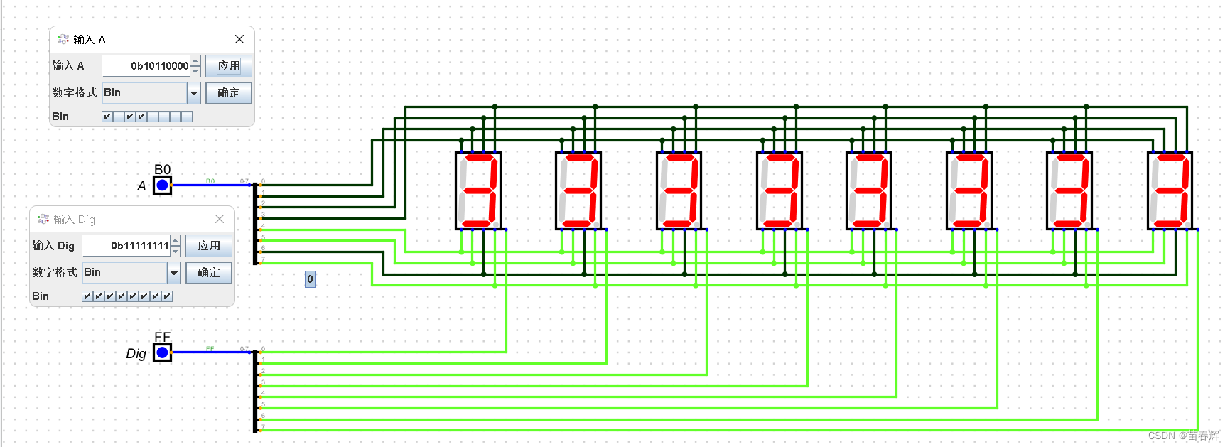
? ? ? ? 我们通过Digital软件对数码管进行仿真,我们可以了解到,上面八位是控制数码管各个段的熄灭与点亮,因为我们用到的数码管是共阳极,所以把对应段的电压拉低就会亮起来。下面八位是控制哪几个数码管亮的。
? ? ? ? 返回看我们的原理图,这里需要两个移位寄存器来存储数据并且发送到数码管,这里用到的移位寄存器是74hc595,它的功能是串行输入并行输出。
移位寄存器的引脚:
- LATCH_CLOCK: 锁存时钟
- SHIFT_CLOCK: 移位时钟
- A: 数据输入信号管脚
- QA~QH: 数据信号转化出来的高低电平
- SQH: 串行数据输出管脚
????????原理图中第一个移位寄存器从14号NIX DI引脚输入数据,然后通过9号引脚,输出到另外一个移位寄存器的14口,这两两个寄存器就实现了串联。
? ? ? ? 由对应串脚分析,原理图左边寄存器控制的是数码管对应段的亮灭,右边寄存器控制的是哪几个数码管亮。

? ? ? ??74hc595工作原理:它的芯片内部有一个移位寄存器和一个锁存寄存器,当1接收到串行数据时候,开始从高位一位一位的取出来给14号引脚 赋值,没取一位移位寄存器必须有一个上升沿才会把数据移位存储在移位寄存器中,存入到移位寄存器的数据通过NIX_RCK的一次上升沿存储到锁存寄存器中,此时数据并没有被输出,最后当13号输出信号使能引脚为低电平时,数据才会发送到数码管,因为这里我么你直接将13号引脚接地,所以数据直接就会被发送。
? ? ? ? 这里注意的是数据从原理图右边寄存器输入,先放入右边寄存器的移位寄存器中,然后再放入自己的移位锁存器中,然后各自进行锁存,最后一起发送到数码管中,所以在写代码时先给的数据是控制数码管对应段的亮灭的,后给的代码是控制都哪几个锁存器工作。
代码展示
数码管简单显示
#include "GPIO.h"
#include "Delay.h"


#define NIX_DI P44  // 数据输入引脚
#define NIX_RCK P43  // 锁存寄存器时钟信号引脚
#define NIX_SCK P42  // 移位寄存器时钟信号引脚

void GPIO_config(void) {
	GPIO_InitTypeDef	GPIO_InitStructure;		//结构定义
	GPIO_InitStructure.Pin  = GPIO_Pin_2 |GPIO_Pin_3 |GPIO_Pin_4;		//指定要初始化的IO,
	GPIO_InitStructure.Mode = GPIO_PullUp;	//指定IO的输入或输出方式,GPIO_PullUp,GPIO_HighZ,GPIO_OUT_OD,GPIO_OUT_PP
	GPIO_Inilize(GPIO_P4, &GPIO_InitStructure);//初始化
}

void main(){
	int i ;
	//1. 准备两个字节: 显示什么数据 以及 哪个数码管要显示
	u8 dat = 0xB0 ; // 让数码管显示 数字3  10110000
	u8 idx = 0x03 ; // 这是 0000 0011 前两个数码管都显示


	//2. 设置IO模式
	GPIO_config();

	//3. 一位一位的放数据:: 先放高位


	//3.1 先放显示什么数字::
	for(i = 7 ; i >= 0 ; i--){

		//先取出具体的位,只要不是0,那么输出的就是高电平  会设置成 1
		NIX_DI = dat & (1<<i);

		//做出来一个移位时钟信号(上升沿信号)
		NIX_SCK = 0 ;
		NOP2();
		NIX_SCK = 1 ;
		NOP2();
	}


	//3.2 再放哪一个数码管显示
	/*
		1111 1111
	  0000 1000
	& --------------
	0000 1000  = 8  >0 ? 1 : 0
	*/
	for(i = 7 ; i >= 0 ; i--){
		NIX_DI = idx & (1 << i);

			//做出来一个移位时钟信号(上升沿信号)
		NIX_SCK = 0 ;
		NOP2();
		NIX_SCK = 1 ;
		NOP2();
	}


	//3.3 在来一个锁存寄存器的上升沿
	NIX_RCK = 0;
	NOP2();
	NIX_RCK = 1;
	NOP2();


	while(1){

	}
}
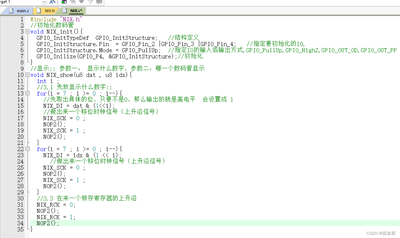
数码管显示(封装)
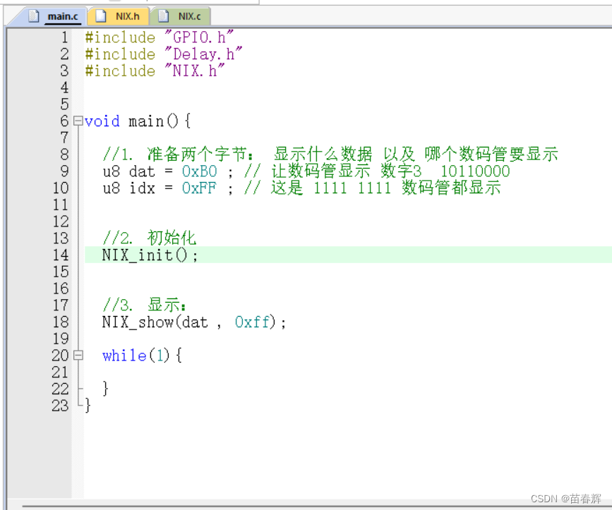
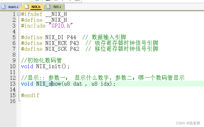
数码管显示(封装数组)
我们把基本数码管展示的内容做成一个数组,直接用数组索引传入数据会更方便。

当然下面对应的代码dat部分都要用LED_TABLE[index]代替,这里不做演示。
数码管跑马灯
main.c:
#include "GPIO.h"
#include "Delay.h"
#include "NIX.h"


void main(){
	int i ;

	//1. 初始化
	NIX_init();

	//2. 显示


	while(1){

		for(i = 0 ; i < 8 ; i ++){

			//参数一: 数组的下标 . 0 ~ 7 .参数二就是让哪一个数码管显示
			NIX_show( i ,  1<<i);

			delay_ms(200);
		}
	}


}
NIX.h:
#ifndef	__NIX_H
#define	__NIX_H
#include "GPIO.h"

#define NIX_DI P44  // 数据输入引脚
#define NIX_RCK P43  // 锁存寄存器时钟信号引脚
#define NIX_SCK P42  // 移位寄存器时钟信号引脚

//初始化数码管
void NIX_init();

//显示:: 参数一: 显示什么数字[传递进来的是数组的下标],参数二:哪一个数码管显示
void NIX_show(u8 index , u8 idx);

#endif
NIX.c:
#include "NIX.h"

u8 code LED_TABLE[] =
{
	// 0 	1	 2	-> 9	(索引012...9)
	0xC0,0xF9,0xA4,0xB0,0x99,0x92,0x82,0xF8,0x80,0x90,
	// 0  1. 2. -> 9.	(索引10,11,12....19)
    0x40,0x79,0x24,0x30,0x19,0x12,0x02,0x78,0x00,0x10,
	// . -						(索引20,21)
	0x7F, 0xBF,
	// AbCdEFHJLPqU		(索引22,23,24....33)
	0x88,0x83,0xC6,0xA1,0x86,0x8E,0x89,0xF1,0xC7,0x8C,0x98,0xC1
};


//初始化数码管
void NIX_init(){
	GPIO_InitTypeDef	GPIO_InitStructure;		//结构定义
	GPIO_InitStructure.Pin  = GPIO_Pin_2 |GPIO_Pin_3 |GPIO_Pin_4;		//指定要初始化的IO,
	GPIO_InitStructure.Mode = GPIO_PullUp;	//指定IO的输入或输出方式,GPIO_PullUp,GPIO_HighZ,GPIO_OUT_OD,GPIO_OUT_PP
	GPIO_Inilize(GPIO_P4, &GPIO_InitStructure);//初始化
}

//显示:: 参数一: 显示什么数字[传递进来的是数组的下标],参数二:哪一个数码管显示
void NIX_show(u8 index , u8 idx){

	int i ;

	//3.1 先放显示什么数字::
	for(i = 7 ; i >= 0 ; i--){

		//先取出具体的位,只要不是0,那么输出的就是高电平  会设置成 1
		NIX_DI = LED_TABLE[index] & (1<<i);

		//做出来一个移位时钟信号(上升沿信号)
		NIX_SCK = 0 ;
		NOP2();
		NIX_SCK = 1 ;
		NOP2();
	}


	//3.2 再放哪一个数码管显示
	/*
		1111 1111
	  0000 1000
	& --------------
	0000 1000  = 8  >0 ? 1 : 0
	*/
	for(i = 7 ; i >= 0 ; i--){
		NIX_DI = idx & (1 << i);

			//做出来一个移位时钟信号(上升沿信号)
		NIX_SCK = 0 ;
		NOP2();
		NIX_SCK = 1 ;
		NOP2();
	}


	//3.3 在来一个锁存寄存器的上升沿
	NIX_RCK = 0;
	NOP2();
	NIX_RCK = 1;
	NOP2();

}
总结
? ? ? ? 本期重点就是数码管是如何被点亮的,需要大家明白移位寄存器的主要引脚和工作原理。下期再见!
本文来自互联网用户投稿,该文观点仅代表作者本人,不代表本站立场。本站仅提供信息存储空间服务,不拥有所有权,不承担相关法律责任。 如若内容造成侵权/违法违规/事实不符,请联系我的编程经验分享网邮箱:chenni525@qq.com进行投诉反馈,一经查实,立即删除!
- Python教程
- 深入理解 MySQL 中的 HAVING 关键字和聚合函数
- Qt之QChar编码(1)
- MyBatis入门基础篇
- 用Python脚本实现FFmpeg批量转换
- 9.云原生存储之ceph在k8s中应用及问题处理
- Java语言中的加密技术解析与实现
- 51单片机四位数码管计算器 Proteus仿真程序
- Java毕业设计第96期-基于springboot的图书后台管理系统
- 代码随想录算法训练营第三十六天| 435.无重叠区间、763.划分字母区间、56.合并区间
- ARM_Linux的交叉开发以及交叉编译器
- 基于Python的理财和记账系统-论文、源码、开题报告
- 道路交通调控数据监控大屏:城市交通的智慧引领者
- 基于改进蝙蝠算法的三维航线规划算法
- CISP培训强化研发团队,确保金融科技发展安全无忧