构建库函数雏形(以GPIO为例)
发布时间:2024年01月22日
构建库函数雏形
寄存器 ? 固件库 \textbf{寄存器}\Rightarrow\textbf{固件库} 寄存器?固件库
进行外设结构体定义
将之前中的头文件重新定义:
/*片上外设基地址  */
#define PERIPH_BASE           ((unsigned int)0x40000000)

/*总线基地址 */
#define AHB1PERIPH_BASE       (PERIPH_BASE + 0x00020000)

/*GPIO外设基地址*/
#define GPIOF_BASE            (AHB1PERIPH_BASE + 0x1400)


/*RCC外设基地址*/
#define RCC_BASE              (AHB1PERIPH_BASE + 0x3800)

/*RCC的AHB1时钟使能寄存器地址,强制转换成指针*/
#define RCC_AHB1ENR				*(unsigned int*)(RCC_BASE+0x30)


/* 外设结构体定义 */
typedef  unsigned int uint32;
typedef  unsigned int uint16;

typedef struct{
	uint32 MODER;
	uint32 OTYPER;
	uint32 OSPEEDR;
	uint32 PUPDR;
	uint32 IDR;
	uint32 ODR;
	uint16 BSRRH;
	uint16 BSRRL;
	uint32 LCKR;
	uint32 AFRL;
	uint32 AFRH;
}GPIO_TYPEDEF;

#define GPIOF ((GPIO_TYPEDEF*)GPIOF_BASE) //将GPIOF定义为GPIO_TYPEDEF类型的GPIO_BASE
构建置位和复位函数
在嵌入式系统中,BSRRL 和 BSRRH 是用于设置和复位特定引脚的寄存器位。这两个寄存器通常用于直接操作微控制器上的GPIO(General Purpose Input/Output)引脚。
-
BSRRL(Bit Set Register High/Low):用于将指定的引脚置位(设置为高电平)。通过写入1到BSRRL寄存器的特定位,相应引脚将被设置为高电平。 -
BSRRH(Bit Reset Register High/Low):用于将指定的引脚复位(设置为低电平)。通过写入1到BSRRH寄存器的特定位,相应引脚将被设置为低电平。
 /*
  *函数功能:设置引脚为高电平
  *参数说明:GPIOx,该参数为GPIO_TypeDef类型的指针,指向GPIO端口的地址
  * 			  GPIO_Pin:选择要设置的GPIO端口引脚,可输入宏GPIO_Pin_0-15,
	*										表示GPIOx端口的0-15号引脚。
  */
void GPIO_SetBits(GPIO_TypeDef* GPIOx, uint16_t GPIO_Pin)
{
	/*设置GPIOx端口BSRRL寄存器的第GPIO_Pin位,使其输出高电平*/
	/*因为BSRR寄存器写0不影响,
	  GPIO_Pin只是对应位为1,其它位均为0,所以可以直接赋值*/

  GPIOx->BSRRL = GPIO_Pin;
}

 /*
  *函数功能:设置引脚为低电平
  *参数说明:GPIOx,该参数为GPIO_TypeDef类型的指针,指向GPIO端口的地址
  * 			  GPIO_Pin:选择要设置的GPIO端口引脚,可输入宏GPIO_Pin_0-15,
	*										表示GPIOx端口的0-15号引脚。
  */
void GPIO_ResetBits(GPIO_TypeDef* GPIOx, uint16_t GPIO_Pin)
{
	/*设置GPIOx端口BSRRH寄存器的第GPIO_Pin位,使其输出低电平*/
	/*因为BSRR寄存器写0不影响,
	GPIO_Pin只是对应位为1,其它位均为0,所以可以直接赋值*/

  GPIOx->BSRRH = GPIO_Pin;
}
进行库函数的自定义
step ? I: \textbf{step I:} step?I: 对端口进行输出数据类型枚举
/* GPIO端口配置模式的枚举定义 */
typedef enum{
  GPIO_Mode_IN   = 0x00, /*!< 输入模式 */
  GPIO_Mode_OUT  = 0x01, /*!< 输出模式 */
  GPIO_Mode_AF   = 0x02, /*!< 复用模式 */
  GPIO_Mode_AN   = 0x03  /*!< 模拟模式 */
}GPIOMode_TypeDef;

/* GPIO输出类型枚举定义 */
typedef enum{
  GPIO_OType_PP = 0x00,	/*!< 推挽模式 */
  GPIO_OType_OD = 0x01	/*!< 开漏模式 */
}GPIOOType_TypeDef;


/* GPIO输出速率枚举定义 */
typedef enum{
  GPIO_Speed_2MHz   = 0x00, /*!< 2MHz   */
  GPIO_Speed_25MHz  = 0x01, /*!< 25MHz  */
  GPIO_Speed_50MHz  = 0x02, /*!< 50MHz  */
  GPIO_Speed_100MHz = 0x03  /*!< 100MHz */
}GPIOSpeed_TypeDef;

/* GPIO上/下拉配置枚举定义 */
typedef enum{
  GPIO_PuPd_NOPULL = 0x00, /*浮空*/
  GPIO_PuPd_UP     = 0x01, /*上拉*/
  GPIO_PuPd_DOWN   = 0x02  /*下拉*/
}GPIOPuPd_TypeDef;
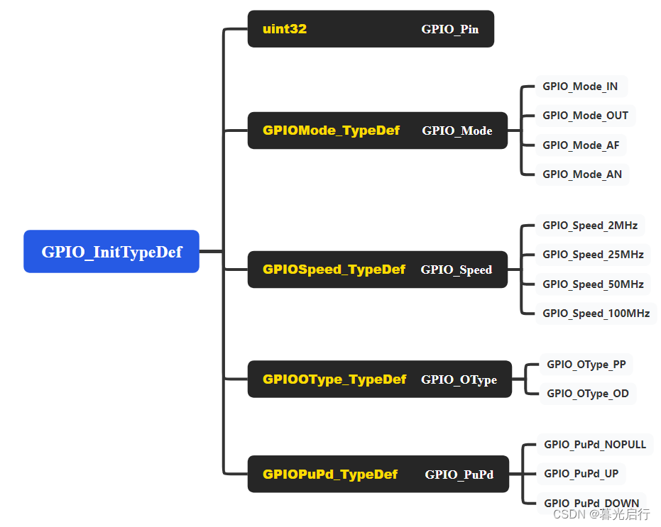
step ? II: \textbf{step II:} step?II:对端口进行结构化描述
/* GPIO初始化结构体类型定义 */
typedef struct {
  uint32_t GPIO_Pin;              /*!< 选择要配置的GPIO引脚
                                        可输入 GPIO_Pin_ 定义的宏 */

  GPIOMode_TypeDef GPIO_Mode;     /*!< 选择GPIO引脚的工作模式
                                       可输入 GPIOMode_TypeDef 定义的枚举值*/

  GPIOSpeed_TypeDef GPIO_Speed;   /*!< 选择GPIO引脚的速率
                                       可输入 GPIOSpeed_TypeDef 定义的枚举值 */

  GPIOOType_TypeDef GPIO_OType;   /*!< 选择GPIO引脚输出类型
                                       可输入 GPIOOType_TypeDef 定义的枚举值*/

  GPIOPuPd_TypeDef GPIO_PuPd;     /*!<选择GPIO引脚的上/下拉模式
                                       可输入 GPIOPuPd_TypeDef 定义的枚举值*/
}GPIO_InitTypeDef;
step ? III: \textbf{step III:} step?III:例化GPIO口

实验实例
main.c部分
闪烁红灯一段时间后闪烁绿灯
#include "stm32f4xx_gpio.h"

//简单的延时函数,让cpu执行无意义指令,消耗时间
//具体延时时间难以计算,以后我们可使用定时器精确延时
void Delay( uint32_t nCount)
{
	for(; nCount != 0; nCount--);
}


int main(void)
{
	GPIO_InitTypeDef GPIO_InitStruct;

	/*开启 GPIOF 时钟,使用外设时都要先开启它的时钟*/
	RCC->AHB1ENR |= (1<<5);

	/* LED 端口初始化 */

	/*初始化PF6引脚*/
	/*选择要控制的GPIO引脚*/
	GPIO_InitStruct.GPIO_Pin = GPIO_Pin_6;
	/*设置引脚模式为输出模式*/
	GPIO_InitStruct.GPIO_Mode = GPIO_Mode_OUT;
	/*设置引脚的输出类型为推挽输出*/
	GPIO_InitStruct.GPIO_OType = GPIO_OType_PP;
	/*设置引脚为上拉模式*/
	GPIO_InitStruct.GPIO_PuPd = GPIO_PuPd_UP;
	/*设置引脚速率为2MHz */
	GPIO_InitStruct.GPIO_Speed = GPIO_Speed_2MHz;
	/*调用库函数,使用上面配置的GPIO_InitStructure初始化GPIO*/
	GPIO_Init(GPIOF, &GPIO_InitStruct);

	/*使引脚输出低电平,点亮LED1*/
	GPIO_ResetBits(GPIOF,GPIO_Pin_6);

	/*延时一段时间*/
	Delay(0xFFFFFF);

	/*使引脚输出高电平,关闭LED1*/
	GPIO_SetBits(GPIOF,GPIO_Pin_6);

	/*初始化PF7引脚*/
	GPIO_InitStruct.GPIO_Pin = GPIO_Pin_7;
	GPIO_Init(GPIOF,&GPIO_InitStruct);

	/*使引脚输出低电平,点亮LED2*/
	GPIO_ResetBits(GPIOF,GPIO_Pin_7);

}

// 函数为空,目的是为了骗过编译器不报错
void SystemInit(void){
}
stm32f4xx_gpio.h部分
#include "stm32f4xx.h"


/*GPIO引脚号定义*/
#define GPIO_Pin_0                 ((uint16_t)0x0001)  /*!< 选择Pin0 (1<<0) */
#define GPIO_Pin_1                 ((uint16_t)0x0002)  /*!< 选择Pin1 (1<<1)*/
#define GPIO_Pin_2                 ((uint16_t)0x0004)  /*!< 选择Pin2 (1<<2)*/
#define GPIO_Pin_3                 ((uint16_t)0x0008)  /*!< 选择Pin3 (1<<3)*/
#define GPIO_Pin_4                 ((uint16_t)0x0010)  /*!< 选择Pin4 */
#define GPIO_Pin_5                 ((uint16_t)0x0020)  /*!< 选择Pin5 */
#define GPIO_Pin_6                 ((uint16_t)0x0040)  /*!< 选择Pin6 */
#define GPIO_Pin_7                 ((uint16_t)0x0080)  /*!< 选择Pin7 */
#define GPIO_Pin_8                 ((uint16_t)0x0100)  /*!< 选择Pin8 */
#define GPIO_Pin_9                 ((uint16_t)0x0200)  /*!< 选择Pin9 */
#define GPIO_Pin_10                ((uint16_t)0x0400)  /*!< 选择Pin10 */
#define GPIO_Pin_11                ((uint16_t)0x0800)  /*!< 选择Pin11 */
#define GPIO_Pin_12                ((uint16_t)0x1000)  /*!< 选择Pin12 */
#define GPIO_Pin_13                ((uint16_t)0x2000)  /*!< 选择Pin13 */
#define GPIO_Pin_14                ((uint16_t)0x4000)  /*!< 选择Pin14 */
#define GPIO_Pin_15                ((uint16_t)0x8000)  /*!< 选择Pin15 */
#define GPIO_Pin_All               ((uint16_t)0xFFFF)  /*!< 选择全部引脚 */


/**
  * GPIO端口配置模式的枚举定义
  */
typedef enum
{
  GPIO_Mode_IN   = 0x00, /*!< 输入模式 */
  GPIO_Mode_OUT  = 0x01, /*!< 输出模式 */
  GPIO_Mode_AF   = 0x02, /*!< 复用模式 */
  GPIO_Mode_AN   = 0x03  /*!< 模拟模式 */
}GPIOMode_TypeDef;

/**
  * GPIO输出类型枚举定义
  */
typedef enum
{
  GPIO_OType_PP = 0x00,	/*!< 推挽模式 */
  GPIO_OType_OD = 0x01	/*!< 开漏模式 */
}GPIOOType_TypeDef;


/**
  * GPIO输出速率枚举定义
  */
typedef enum
{
  GPIO_Speed_2MHz   = 0x00, /*!< 2MHz   */
  GPIO_Speed_25MHz  = 0x01, /*!< 25MHz  */
  GPIO_Speed_50MHz  = 0x02, /*!< 50MHz  */
  GPIO_Speed_100MHz = 0x03  /*!<100MHz  */
}GPIOSpeed_TypeDef;


/**
  *GPIO上/下拉配置枚举定义
  */
typedef enum
{
  GPIO_PuPd_NOPULL = 0x00,/*浮空*/
  GPIO_PuPd_UP     = 0x01, /*上拉*/
  GPIO_PuPd_DOWN   = 0x02  /*下拉*/
}GPIOPuPd_TypeDef;


/**
  * GPIO初始化结构体类型定义
  */
typedef struct
{
  uint32_t GPIO_Pin;              /*!< 选择要配置的GPIO引脚
                                        可输入 GPIO_Pin_ 定义的宏 */

  GPIOMode_TypeDef GPIO_Mode;     /*!< 选择GPIO引脚的工作模式
                                       可输入 GPIOMode_TypeDef 定义的枚举值*/

  GPIOSpeed_TypeDef GPIO_Speed;   /*!< 选择GPIO引脚的速率
                                       可输入 GPIOSpeed_TypeDef 定义的枚举值 */

  GPIOOType_TypeDef GPIO_OType;   /*!< 选择GPIO引脚输出类型
                                       可输入 GPIOOType_TypeDef 定义的枚举值*/

  GPIOPuPd_TypeDef GPIO_PuPd;     /*!<选择GPIO引脚的上/下拉模式
                                       可输入 GPIOPuPd_TypeDef 定义的枚举值*/
}GPIO_InitTypeDef;


void GPIO_SetBits(GPIO_TypeDef* GPIOx, uint16_t GPIO_Pin);

void GPIO_ResetBits(GPIO_TypeDef* GPIOx, uint16_t GPIO_Pin);

void GPIO_Init(GPIO_TypeDef* GPIOx, GPIO_InitTypeDef* GPIO_InitStruct);
stm32f4xx_gpio.c部分
#include "stm32f4xx_gpio.h"

/**
  *函数功能:设置引脚为高电平
  *参数说明:GPIOx,该参数为GPIO_TypeDef类型的指针,指向GPIO端口的地址
  * 			  GPIO_Pin:选择要设置的GPIO端口引脚,可输入宏GPIO_Pin_0-15,
	*										表示GPIOx端口的0-15号引脚。
  */
void GPIO_SetBits(GPIO_TypeDef* GPIOx, uint16_t GPIO_Pin)
{
	/*设置GPIOx端口BSRRL寄存器的第GPIO_Pin位,使其输出高电平*/
	/*因为BSRR寄存器写0不影响,
	  GPIO_Pin只是对应位为1,其它位均为0,所以可以直接赋值*/

  GPIOx->BSRRL = GPIO_Pin;
}

/**
  *函数功能:设置引脚为低电平
  *参数说明:GPIOx,该参数为GPIO_TypeDef类型的指针,指向GPIO端口的地址
  * 			  GPIO_Pin:选择要设置的GPIO端口引脚,可输入宏GPIO_Pin_0-15,
	*										表示GPIOx端口的0-15号引脚。
  */
void GPIO_ResetBits(GPIO_TypeDef* GPIOx, uint16_t GPIO_Pin)
{
	/*设置GPIOx端口BSRRH寄存器的第GPIO_Pin位,使其输出低电平*/
	/*因为BSRR寄存器写0不影响,
	GPIO_Pin只是对应位为1,其它位均为0,所以可以直接赋值*/

  GPIOx->BSRRH = GPIO_Pin;
}

/**
  *函数功能:初始化引脚模式
  *参数说明:GPIOx,该参数为GPIO_TypeDef类型的指针,指向GPIO端口的地址
  * 			  GPIO_InitTypeDef:GPIO_InitTypeDef结构体指针,指向初始化变量
  */
void GPIO_Init(GPIO_TypeDef* GPIOx, GPIO_InitTypeDef* GPIO_InitStruct)
{
	  uint32_t pinpos = 0x00, pos = 0x00 , currentpin = 0x00;

	/*-- GPIO Mode Configuration --*/
  for (pinpos = 0x00; pinpos < 16; pinpos++)
  {
		/*以下运算是为了通过 GPIO_InitStruct->GPIO_Pin 算出引脚号0-15*/

		/*经过运算后pos的pinpos位为1,其余为0,与GPIO_Pin_x宏对应。pinpos变量每次循环加1,*/
		pos = ((uint32_t)0x01) << pinpos;

		/* pos与GPIO_InitStruct->GPIO_Pin做 & 运算,若运算结果currentpin == pos,
		则表示GPIO_InitStruct->GPIO_Pin的pinpos位也为1,
		从而可知pinpos就是GPIO_InitStruct->GPIO_Pin对应的引脚号:0-15*/
    currentpin = (GPIO_InitStruct->GPIO_Pin) & pos;

		/*currentpin == pos时执行初始化*/
    if (currentpin == pos)
		{
			/*GPIOx端口,MODER寄存器的GPIO_InitStruct->GPIO_Pin对应的引脚,MODER位清空*/
			GPIOx->MODER  &= ~(3 << (2 *pinpos));

			/*GPIOx端口,MODER寄存器的GPIO_Pin引脚,MODER位设置"输入/输出/复用输出/模拟"模式*/
			GPIOx->MODER |= (((uint32_t)GPIO_InitStruct->GPIO_Mode) << (2 *pinpos));

			/*GPIOx端口,PUPDR寄存器的GPIO_Pin引脚,PUPDR位清空*/
			GPIOx->PUPDR &= ~(3 << ((2 *pinpos)));

			/*GPIOx端口,PUPDR寄存器的GPIO_Pin引脚,PUPDR位设置"上/下拉"模式*/
			GPIOx->PUPDR |= (((uint32_t)GPIO_InitStruct->GPIO_PuPd) << (2 *pinpos));

			/*若模式为"输出/复用输出"模式,则设置速度与输出类型*/
			if ((GPIO_InitStruct->GPIO_Mode == GPIO_Mode_OUT) || (GPIO_InitStruct->GPIO_Mode == GPIO_Mode_AF))
			{
				/*GPIOx端口,OSPEEDR寄存器的GPIO_Pin引脚,OSPEEDR位清空*/
				GPIOx->OSPEEDR &= ~(3 << (2 *pinpos));
				/*GPIOx端口,OSPEEDR寄存器的GPIO_Pin引脚,OSPEEDR位设置输出速度*/
				GPIOx->OSPEEDR |= ((uint32_t)(GPIO_InitStruct->GPIO_Speed) << (2 *pinpos));

				/*GPIOx端口,OTYPER寄存器的GPIO_Pin引脚,OTYPER位清空*/
				GPIOx->OTYPER  &= ~(1 << (pinpos)) ;
				/*GPIOx端口,OTYPER位寄存器的GPIO_Pin引脚,OTYPER位设置"推挽/开漏"输出类型*/
				GPIOx->OTYPER |= (uint16_t)(((uint16_t)GPIO_InitStruct->GPIO_OType) << (pinpos));
			}
		}
	}
}
文章来源:https://blog.csdn.net/muguangqixing/article/details/135726332
本文来自互联网用户投稿,该文观点仅代表作者本人,不代表本站立场。本站仅提供信息存储空间服务,不拥有所有权,不承担相关法律责任。 如若内容造成侵权/违法违规/事实不符,请联系我的编程经验分享网邮箱:chenni525@qq.com进行投诉反馈,一经查实,立即删除!
本文来自互联网用户投稿,该文观点仅代表作者本人,不代表本站立场。本站仅提供信息存储空间服务,不拥有所有权,不承担相关法律责任。 如若内容造成侵权/违法违规/事实不符,请联系我的编程经验分享网邮箱:chenni525@qq.com进行投诉反馈,一经查实,立即删除!
最新文章