基于Mcrosemi M2S090T FPGA 的 imx991 SWIR的SLVS解码(一)
目录
一、平台介绍
工程开发平台:Libero Version:20231.0.6 Release:v2023.1
文本编辑器:Sublime text3?
二、器件的简介
1、imx991?SWIR?Image Sensor
- Description :
The IMX991-AABA-C is a diagonal 4.1 mm (Type 1 / 4) CMOS active pixel type solid-state image sensor with a?square pixel array and 0.33 M effective pixels. This chip features a global shutter with variable charge-integration?time. This chip has a wide waveband (0.4 μm to 1.7 μm) with high sensitivity, high resolution, low dark current and?low power consumption. ??
- Features?
◆ CMOS active pixel type dots?
◆ Visible + SWIR wideband sensor (0.4 μm to 1.7 μm)?
◆ Built-in timing adjustment circuit, H/V driver and serial communication circuit?
◆ Global shutter function?
◆ Input frequency?
37.125 MHz / 74.25 MHz / 54 MHz?
◆ Number of recommended recording?pixels: 640 (H) × 512 (V) approx. 0.33 M pixels?
Readout mode?
All - pixel scan mode ??
Vertical / Horizontal 1 / 2 Subsampling mode?
ROI mode?
Vertical / Horizontal‐Normal / Inverted readout mode?
◆ 8-bit / 10-bit / 12-bit A/D converter?
◆ Readout rate?
Maximum frame rate in?
All - pixel scan mode: 8bit : 258.80 frame/s, 10 bit: 240.61 frame/s, 12bit: 137.39 frame/s?
◆ Variable-speed shutter function (resolution 1 H units)?
◆ PGA function?
? ? ? ? 0 dB to 18 dB: Analog Gain (0.1 dB step)?
? ? ? ? 18.1 dB to 42 dB: Analog Gain: 18 dB + Digital Gain: 0.1 dB to 24 dB (0.1 dB step)?
◆ I/O interface?
SLVS (2 ch / 4 ch switching) output?
◆ Recommended exit pupil distance: –100 mm to –∞?
◆ Built-in digital thermometer?
◆ Built-in thermoelectoric cooler?
?
2、M2S090T
M2S090T是Microsemi公司Smartfusion系统的带SOC的FPGA,其架构如下图所示。
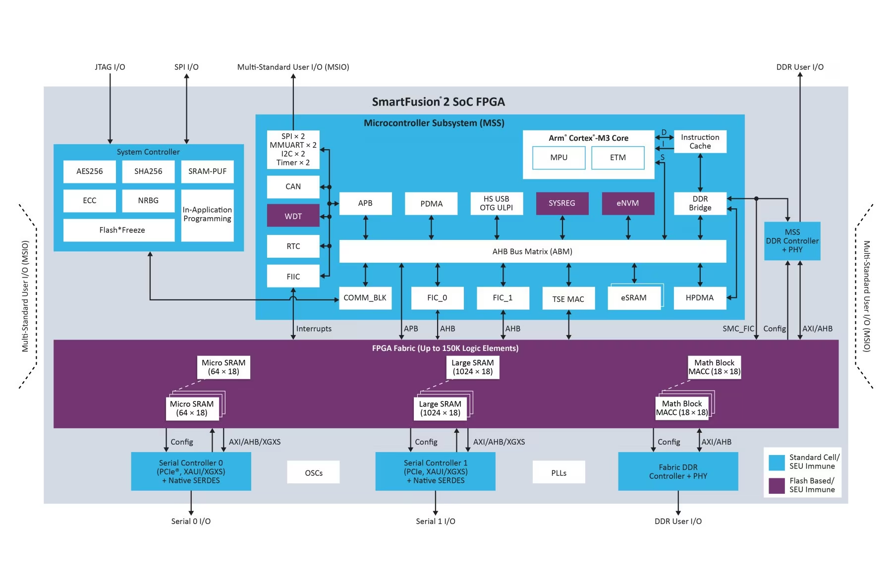
????????M2S090 内部包括主要分两部分,MSS和fabric,其中MSS即为一个cortext M3 ARM核和一些外围接口,fabric部分即为FPGA的逻辑部分。两部分之间可以通过AHB、APB进行通信,另外还有相互的中断信号可用。
????????下面就是Cache Controller Interfaces to Cortex-M3 Processor, AHB Bus Matrix, and MDDR Bridge
三、工程
本工程配置imx991 sensor 为主模式,SLVS 4channel,8bit数据,all scan,656*545分辨率
1、imx991寄存器配置
This sensor has a total of 5376 bytes of registers, composed of registers with address 00h to FFh that correspond to?Chip ID = 02h to 0Ch, 10h to 19h. Use the initial values for empty address. Some registers must be change from the?initial values, so the sensor control side should be capable of setting 5376 bytes.

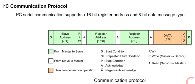
配置寄存有两种总线:IIC和SPI,任选其一,本工程使用IIC总线,上图为寄存器说明的一部分,IIC总线和SPI总线操作地址有所不同。SPI总线时需要先chip ID然后再address;IIC总线就直接address。
工程里定义寄存器值取一部分,如下图所示

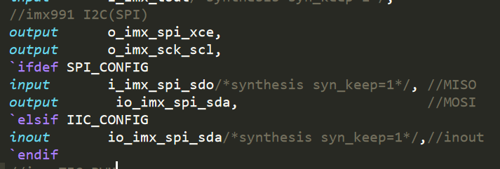
顶层接口的定义如下图所示
以下是IIC接口的例化
//====================================================================================
//
//-----接口总线
//
// IIC or SPI;
//
//通过宏定义文件define.v内的宏变量来控制,当前使用IIC
//

	wire [1:0] isStart;
	wire [15:0] iic_rAddr;
	wire [7:0]  iic_WrData;
	assign isStart    = (sen_reg_sta==4'h0 || sen_reg_sta==4'h2 )? ( (Start_Sig == 1)? ((r_rw==1)?2'b10 : 2'b01) : 2'b00 ) : ((Start_Sig2 == 1)? ((r_rw2==1)?2'b10 : 2'b01) : 2'b00 );
	assign iic_rAddr  = (sen_reg_sta==4'h0 || sen_reg_sta==4'h2 )? rAddr   : conf_addr ;
	assign iic_WrData = (sen_reg_sta==4'h0 || sen_reg_sta==4'h2 )? WrData  : conf_data ;

	iic_bus U_iic
	 (
	      .CLK      ( i_clk      ),
		  .RSTn     ( i_rst_n    ),
		  .Start_Sig( isStart    ),
		  .Addr_Sig ( iic_rAddr  ),
		  .WrData   ( iic_WrData ),
		  .RdData   ( RdData     ),
		  .Done_Sig ( Done_Sig   ),
	      .SCL      ( o_i2c_scl  ),
		  .SDA      ( io_i2c_sdi )
	 );


	assign o_spi_cs   = 1;
-----------------------------------------------------------------------------------------------------------------
凡有FPGA方面开发需求的朋友,欢迎发信息联系交流合作!
本文来自互联网用户投稿,该文观点仅代表作者本人,不代表本站立场。本站仅提供信息存储空间服务,不拥有所有权,不承担相关法律责任。 如若内容造成侵权/违法违规/事实不符,请联系我的编程经验分享网邮箱:chenni525@qq.com进行投诉反馈,一经查实,立即删除!
- Python教程
- 深入理解 MySQL 中的 HAVING 关键字和聚合函数
- Qt之QChar编码(1)
- MyBatis入门基础篇
- 用Python脚本实现FFmpeg批量转换
- Spring Boot整合 EasyExcel 实现复杂 Excel 表格的导入与导出功能
- 芯知识 | 什么是音频蓝牙播放语音芯片?
- 使用css动画animation及@keyframes实现图片持续放大缩小动画展示
- verilog语法进阶-移位寄存器原语-单输入单输出
- 线程与UI操作
- ssm基于JAVA的驾校信息管理系统设计论文
- 安装DevEcoStudio
- mysql数据库知识点
- 浊度水质分析仪的功能特性,及其在环境监测中的重要作用
- Spring Boot “How-to” 指南中文文档-下