osg::DrawElements*系列函数及GL_QUAD_STRIP、GL_QUADS绘制四边形效率对比
目录
3.?GL_QUADS、GL_QUAD_STRIP用法及不同点
1. 前言
? ? ? 利用osg绘制图元,如:三角形、四边形等,一般用osg::PrimitiveSet类。其派生出了很多子类,如下图所示:

图1?
在开发中,用DrawElements*系列函数和osg::DrawArrays函数绘制图元比较多,本文以绘制四边形为例子,以osg::DrawElementsUShort、osg::DrawArrays来讲解怎样绘制四边形,及GL_QUAD_STRIP、GL_QUAD的不同、它们之间的效率。
2. osg::DrawElements*系列函数用法说明
? ? ? osg::DrawElements*系列函数osg::DrawElementsUShort、osg::DrawElementsUBye、osg::DrawElementsUInt从osg::DrawElements派生,而osg::DrawElements对应OPenGL的glDrawElements函数,关于glDrawElements函数用法,请参考:
? ?osg::DrawArrays?类在直接从数组读取顶点数据时效果很好,没有间隙。 但是,当同一个顶点可以属于一个对象的多个面时,它就不那么有效了。 考虑这个例子:
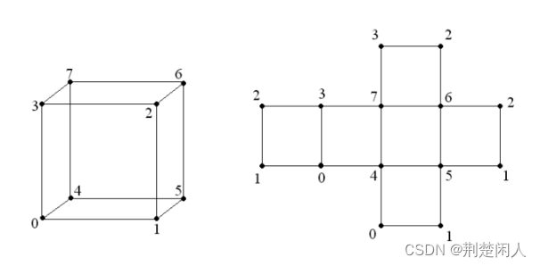
图2?
一个立方体有八个顶点。 然而,从图中可以看出(我们正在考虑将一个立方体扫到一个平面上),一些顶点属于多个面。 如果我们构建一个包含 12 个三角形面的立方体(注:虽然是绘制四边形,但GPU等硬件在真正绘制时,是用两个三角形来拼出一个四边形的,对于硬件来说绘制2个三角形比直接一个四边形效率更高,故6个四边形其实内部绘制是12个三角形绘制的),那么这些顶点将重复,而不是 8 个顶点的数组,我们将得到 36 个顶点的数组,其中大部分实际上是相同的顶点!?
? ? ? 在OSG中,有类?osg::DrawElementsUInt、?osg::DrawElementsUByte和?osg::DrawElementsUShort,它们使用顶点索引数组作为数据,旨在解决上述问题。 索引数组存储描述几何体的面和其他元素的图元顶点的索引。 将这些类应用于立方体时,存储八个顶点的数据就足够了,这些顶点通过索引数组与面相关联。
? ?osg::DrawElements*?类型的类的设计方式与标准?std::vector?类的设计方式相同。 此代码可用于添加索引。如:
osg::ref_ptr<osg::DrawElementsUInt> de = new osg::DrawElementsUInt(GL_TRIANGLES);
de->push_back(0);
de->push_back(1);
de->push_back(2);
de->push_back(3);
de->push_back(0);
de->push_back(2);
此代码定义图2中所示的立方体的正面。考虑另一个说明性的例子——八面体。
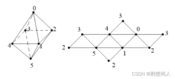
图3?
很有趣,因为它只包含六个顶点,但每个顶点已经在四个三角形面中了! 我们可以使用?osg::DrawArrays?创建一个包含 24 个顶点的数组来显示所有八个面。 然而,我们将采取不同的方式——我们将顶点存储在一个包含六个元素的数组中,并使用类?osg::DrawElementsUInt?生成面。
main.h
#ifndef     MAIN_H
#define     MAIN_H
#include<osg/Geometry>
#include<osg/Geode>
#include<osgUtil/SmoothingVisitor>
#include<osgViewer/Viewer>
#endif
?main.cpp
#include"main.h"
int main(int argc, char *argv[]){

    osg::ref_ptr<osg::Vec3Array> vertices = new osg::Vec3Array(6);
    (*vertices)[0].set( 0.0f,  0.0f,  1.0f);
    (*vertices)[1].set(-0.5f, -0.5f,  0.0f);
    (*vertices)[2].set( 0.5f, -0.5f,  0.0f);
    (*vertices)[3].set( 0.5f,  0.5f,  0.0f);
    (*vertices)[4].set(-0.5f,  0.5f,  0.0f);
    (*vertices)[5].set( 0.0f,  0.0f, -1.0f);

    osg::ref_ptr<osg::DrawElementsUInt> indices = new osg::DrawElementsUInt(GL_TRIANGLES, 24);
    (*indices)[ 0] = 0; (*indices)[ 1] = 1; (*indices)[ 2] = 2;
    (*indices)[ 3] = 0; (*indices)[ 4] = 4; (*indices)[ 5] = 1;
    (*indices)[ 6] = 4; (*indices)[ 7] = 5; (*indices)[ 8] = 1;
    (*indices)[ 9] = 4; (*indices)[10] = 3; (*indices)[11] = 5;
    (*indices)[12] = 3; (*indices)[13] = 2; (*indices)[14] = 5;
    (*indices)[15] = 1; (*indices)[16] = 5; (*indices)[17] = 2;
    (*indices)[18] = 3; (*indices)[19] = 0; (*indices)[20] = 2;
    (*indices)[21] = 0; (*indices)[22] = 3; (*indices)[23] = 4;

    osg::ref_ptr<osg::Geometry> geom = new osg::Geometry;
    geom->setVertexArray(vertices.get());
    geom->addPrimitiveSet(indices.get());

    osgUtil::SmoothingVisitor::smooth(*geom);

    osg::ref_ptr<osg::Geode> root = new osg::Geode;
    root->addDrawable(geom.get());

    osgViewer::Viewer viewer;
    viewer.setSceneData(root.get());

    return viewer.run();
}上述代码先创建一个有六个顶点的数组,然后使用指针解引用操作和?operator []?操作符寻址其坐标向量 赋值。别忘了?osg::Array?是?std::vector?的派生类。然后为面创建为顶点索引列表。面将是三角形的,共有 8 个,这意味着索引列表应包含 24 个元素。 面索引按顺序进入此数组:例如,面 0 由顶点 0、1 和 2 组成; 面 1 - 顶点 0、4 和 1; 面 2 - 顶点 4、5 和 1,依此类推。 顶点按逆时针顺序列出,如果你看正面(见图3)。
3.?GL_QUADS、GL_QUAD_STRIP用法及不同点
? ? ??GL_QUADS:绘制一系列四边形,首先使用顶点V0、V1、V2、V3绘制第1个四边形,然后是V4、V5、V6、V7绘制第2个四边形,接下来以次类推,如果顶点个数n不是4的倍数,最后1个、2个、3个顶点被忽略。注意:如果四边形之间的顶点坐标不相同,则这些四边形是分离的,如下:
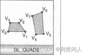
图4?
GL_QUAD_STRIP:绘制一系列四边形,首先使用顶点V0、V1、V3、V2绘制第1个四边形,接着是V2、V3、V5、V4,然后是V4、V5、V7、V6。以此类推。顶点个数n至少要大于4,否则不会绘制任何四边形。如果n是奇数,最后一点顶点就被忽略。如下:
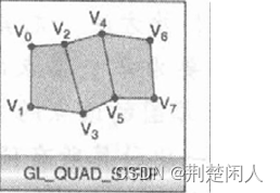
图5?
GL_QUAD_STRIP画出一组共享边的四边形。对于较小的模型,共享边的差异可以忽略不计;对于较大的模型,使用GL_QUAD_STRIP意味着显著地节省了计算次数。从第一对顶点开始,相邻的两对定点被定义成一个四边形。定点?2n-1、2n、2n+2和2n+1定义了第n个四边形。有|V|/2-1个四边形将被绘制,|V|代表顶点的个数,如果|V|小于4,OpenGL将不会绘制任何图形。所有四边形将以逆时针顺序排列,互相连接形成四边形带。注意用来构成四边形的顶点顺序和使用GL_QUADS时的顺序是不同的,每一个四边形的第二对定点被逆向使用,以使每一个四边形顶点能被一致地定义。??
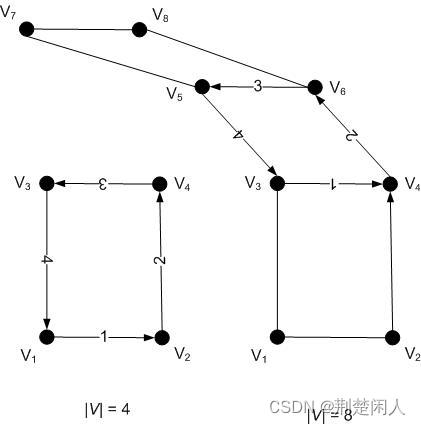
图6?
4.?效率对比
? ? ? ?本节以osg::DrawElements*系列函数及GL_QUAD_STRIP、GL_QUADS绘制四边形,以看看它们之间的效率差别。绘制10个连接的立方体如下:
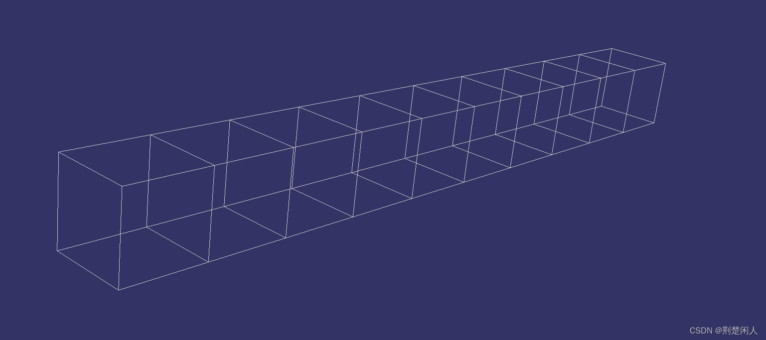
图7
代码如下:
// QUAD_STRIP.cpp : 此文件包含 "main" 函数。程序执行将在此处开始并结束。
//

#include<osgViewer/Viewer>
#include<osgViewer/ViewerEventHandlers>
#include<osg/PolygonMode>
#include<iostream>
//const auto g_quadCount = 1000000;
const auto g_quadCount = 10;

osg::ref_ptr<osg::Geode> createQuads3()
{
	osg::ref_ptr<osg::Geode> spGeode = new osg::Geode;// Geode是Node的派生类,为了绘制图元的管理类

	osg::ref_ptr<osg::Geometry> spGeometory = new osg::Geometry;
	spGeode->addChild(spGeometory);

	osg::ref_ptr<osg::Vec3Array> spCoordsArray = new osg::Vec3Array;
	auto offset = 0;
    int nGeomeryCount = 0;
   while (true)
   {
	   // 前面
	   spCoordsArray->push_back(osg::Vec3d(-1.0, -1.0 + offset, -1.0));  // 前左下顶点  V1
	   spCoordsArray->push_back(osg::Vec3d(1.0, -1.0 + offset, -1.0));   // 前右下顶点  V2
	   spCoordsArray->push_back(osg::Vec3d(-1.0, -1.0 + offset, 1.0));   // 前左上顶点  V3。注意:前左上顶点才是第3个顶点,而不是前右上顶点
	   spCoordsArray->push_back(osg::Vec3d(1.0, -1.0 + offset, 1.0));    // 前右上顶点  V4

	   spCoordsArray->push_back(osg::Vec3d(-1.0, 1.0 + offset, 1.0));    // V5
	   spCoordsArray->push_back(osg::Vec3d(1.0, 1.0 + offset, 1.0));     // V6
	   spCoordsArray->push_back(osg::Vec3d(-1.0, 1.0 + offset, -1.0));   // V7
	   spCoordsArray->push_back(osg::Vec3d(1.0, 1.0 + offset, -1.0));    // V8

	   spCoordsArray->push_back(osg::Vec3d(-1.0, -1.0 + offset, -1.0));    // V9
	   spCoordsArray->push_back(osg::Vec3d(1.0, -1.0 + offset, -1.0));    // V10

	   offset += 2; // y轴方向上宽度为2
	   nGeomeryCount++;
	   if (g_quadCount == nGeomeryCount)
	   {
		   break;
	   }
   }

   spGeometory->setVertexArray(spCoordsArray);
   spGeometory->addPrimitiveSet(new osg::DrawArrays(GL_QUAD_STRIP, 0, spCoordsArray->size()));

   return spGeode;
}

osg::ref_ptr<osg::Geode> createQuads2()
{
	osg::ref_ptr<osg::Geode> spGeode = new osg::Geode;// Geode是Node的派生类,为了绘制图元的管理类

	osg::ref_ptr<osg::Geometry> spGeometory = new osg::Geometry;
	spGeode->addChild(spGeometory);
	//spGeode->addDrawable(spGeometory);// 可以将addChild替换为这句。

	osg::ref_ptr<osg::Vec3Array> spCoordsArray = new osg::Vec3Array;
	auto totalVertCount = g_quadCount * 8;
	osg::DrawElementsUShort* pDrawElemt = new osg::DrawElementsUShort(GL_QUADS, 24 * g_quadCount); // 立方体共8个顶点,每个顶点重复了3次

	auto iVertCount = 0;
	for (auto offset = 0; ; offset += 2)
	{
		spCoordsArray->push_back(osg::Vec3d(1.0, -1.0 + offset, -1.0));  // 0
		spCoordsArray->push_back(osg::Vec3d(1.0, -1.0 + offset, 1.0));   // 1
		spCoordsArray->push_back(osg::Vec3d(-1.0, -1.0 + offset, 1.0));    // 2
		spCoordsArray->push_back(osg::Vec3d(-1.0, -1.0 + offset, -1.0));   // 3

		iVertCount += 4;
		if (iVertCount >= totalVertCount)
		{
			break;
		}
	}

	for (auto guadIndex = 0; guadIndex < g_quadCount; ++guadIndex)
	{
		auto nElementIndex = guadIndex * 24;

		// 右侧面
		auto temp = 4 * guadIndex;
		(*pDrawElemt)[0 + nElementIndex] = 0 + temp;
		(*pDrawElemt)[1 + nElementIndex] = 4 + temp;
		(*pDrawElemt)[2 + nElementIndex] = 5 + temp;
		(*pDrawElemt)[3 + nElementIndex] = 1 + temp;

		// 前面
		if (0 == guadIndex % 2)// 前一个立方体的后面和后一个立方体的前面重合,故只绘制一个
		{
			(*pDrawElemt)[4 + nElementIndex] = 0 + temp;
			(*pDrawElemt)[5 + nElementIndex] = 1 + temp;
			(*pDrawElemt)[6 + nElementIndex] = 2 + temp;
			(*pDrawElemt)[7 + nElementIndex] = 3 + temp;
		}

		// 左侧面
		(*pDrawElemt)[8 + nElementIndex] = 3 + temp;
		(*pDrawElemt)[9 + nElementIndex] = 7 + temp;
		(*pDrawElemt)[10 + nElementIndex] = 6 + temp;
		(*pDrawElemt)[11 + nElementIndex] = 2 + temp;

		// 上面
		(*pDrawElemt)[12 + nElementIndex] = 1 + temp;
		(*pDrawElemt)[13 + nElementIndex] = 5 + temp;
		(*pDrawElemt)[14 + nElementIndex] = 6 + temp;
		(*pDrawElemt)[15 + nElementIndex] = 2 + temp;

		// 后面
		(*pDrawElemt)[16 + nElementIndex] = 4 + temp;
		(*pDrawElemt)[17 + nElementIndex] = 5 + temp;
		(*pDrawElemt)[18 + nElementIndex] = 6 + temp;
		(*pDrawElemt)[19 + nElementIndex] = 7 + temp;

		// 底面
		(*pDrawElemt)[20 + nElementIndex] = 0 + temp;
		(*pDrawElemt)[21 + nElementIndex] = 4 + temp;
		(*pDrawElemt)[22 + nElementIndex] = 7 + temp;
		(*pDrawElemt)[23 + nElementIndex] = 3 + temp;

	}

	spGeometory->setVertexArray(spCoordsArray);
	spGeometory->addPrimitiveSet(pDrawElemt);

	return spGeode;
}

osg::Geode* createQuads1()
{
	auto pGeode = new osg::Geode;

	auto pGeomery = new osg::Geometry;
	pGeode->addChild(pGeomery);
	auto spCoordsArray = new osg::Vec3Array;
	auto offset = 0;
	int nGeomeryCount = 0;
	while (true)
	{
		// 右侧面
		spCoordsArray->push_back(osg::Vec3d(1.0, -1.0 + offset, -1.0));  // 前右下顶点
		spCoordsArray->push_back(osg::Vec3d(1.0, 1.0 + offset, -1.0));   // 后右下顶点
		spCoordsArray->push_back(osg::Vec3d(1.0, 1.0 + offset, 1.0));    // 后右上顶点
		spCoordsArray->push_back(osg::Vec3d(1.0, -1.0 + offset, 1.0));   // 前右上顶点

		// 前面
		spCoordsArray->push_back(osg::Vec3d(1.0, -1.0 + offset, -1.0));  // 右下顶点
		spCoordsArray->push_back(osg::Vec3d(1.0, -1.0 + offset, 1.0));   // 右上顶点
		spCoordsArray->push_back(osg::Vec3d(-1.0, -1.0 + offset, 1.0));  // 左上顶点
		spCoordsArray->push_back(osg::Vec3d(-1.0, -1.0 + offset, -1.0)); // 左下顶点

		// 左侧面
		spCoordsArray->push_back(osg::Vec3d(-1.0, -1.0 + offset, -1.0));  // 前左下顶点
		spCoordsArray->push_back(osg::Vec3d(-1.0, -1.0 + offset, 1.0));   // 前左上顶点
		spCoordsArray->push_back(osg::Vec3d(-1.0, 1.0 + offset, 1.0));    // 后左上顶点
		spCoordsArray->push_back(osg::Vec3d(-1.0, 1.0 + offset, -1.0));   // 后左下顶点

		// 后面
		spCoordsArray->push_back(osg::Vec3d(1.0, 1.0 + offset, -1.0));    // 后下顶点
		spCoordsArray->push_back(osg::Vec3d(1.0, 1.0 + offset, 1.0));     // 后上顶点
		spCoordsArray->push_back(osg::Vec3d(-1.0, 1.0 + offset, 1.0));    // 左上顶点
		spCoordsArray->push_back(osg::Vec3d(-1.0, 1.0 + offset, -1.0));   // 左下顶点

		// 上面
		spCoordsArray->push_back(osg::Vec3d(1.0, -1.0 + offset, 1.0));     // 前右顶点
		spCoordsArray->push_back(osg::Vec3d(1.0, 1.0 + offset, 1.0));      // 后右顶点
		spCoordsArray->push_back(osg::Vec3d(-1.0, 1.0 + offset, 1.0));     // 后左顶点
		spCoordsArray->push_back(osg::Vec3d(-1.0, -1.0 + offset, 1.0));    // 前左顶点

		// 底面
		spCoordsArray->push_back(osg::Vec3d(1.0, -1.0 + offset, -1.0));     // 前右顶点
		spCoordsArray->push_back(osg::Vec3d(1.0, 1.0 + offset, -1.0));     // 后右顶点
		spCoordsArray->push_back(osg::Vec3d(-1.0, 1.0 + offset, -1.0));    // 后左顶点
		spCoordsArray->push_back(osg::Vec3d(-1.0, -1.0 + offset, -1.0));   // 前左顶点

		offset += 2; // y轴方向上宽度为2
		nGeomeryCount++;
		if (g_quadCount == nGeomeryCount)
		{
			break;
		}
	}

	pGeomery->setVertexArray(spCoordsArray);
	pGeomery->addPrimitiveSet(new osg::DrawArrays(GL_QUADS, 0, spCoordsArray->size()));

	return pGeode;
}

int main()
{
    auto pRoot = new osg::Group;

	auto pGeode = createQuads3();
	pGeode->getOrCreateStateSet()->setAttribute(
		new osg::PolygonMode(osg::PolygonMode::FRONT_AND_BACK, osg::PolygonMode::LINE));
	pGeode->getOrCreateStateSet()->setMode(GL_LIGHTING, osg::StateAttribute::OFF);

	pRoot->addChild(pGeode);

	auto pViewer = new osgViewer::Viewer;
	auto pStatsHander = new osgViewer::StatsHandler;
	pViewer->addEventHandler(pStatsHander);
	pViewer->setSceneData(pRoot);
	pViewer->run();
}
?当g_quadCount为10时,把第195行代码分别换成createQuads1、createQuads2、createQuads3,在视景器窗体中连续按4次键盘小写s键时,createQuads1函数即用osg::DrawArrays及GL_QUADS各性能指标如下:

图8?osg::DrawArrays及GL_QUADS绘制10个立方体时的各性能指标
createQuads2函数即用osg::DrawElementsUShort及GL_QUADS各性能指标如下:
图9?osg::DrawElementsUShort及GL_QUADS绘制10个立方体时的各性能指标?
createQuads3函数即用osg::DrawArrays及GL_QUAD_STRIP各性能指标如下:?

图10 osg::DrawArrays及GL_QUAD_STRIP绘制10个立方体时的各性能指标??
当绘制的立方体个数为10即立方体个数很少时,这三者在GPU占用、帧率、绘制、裁剪等方面差别不是很大。
当将g_quadCount改为1000000时,?createQuads1函数即用osg::DrawArrays及GL_QUADS各性能指标如下: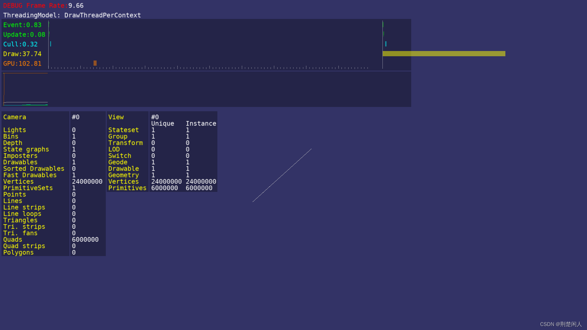
图11 osg::DrawArrays及GL_QUADS绘制1000000个立方体时的各性能指标?
createQuads2函数即用osg::DrawElementsUShort及GL_QUADS各性能指标如下:?
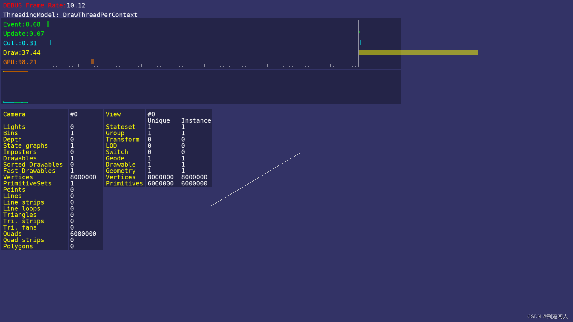
图12 osg::DrawElementsUShort及GL_QUADS绘制1000000个立方体时的各性能指标??
createQuads3函数即用osg::DrawArrays及GL_QUAD_STRIP各性能指标如下:?

图13 osg::DrawArrays及GL_QUAD_STRIP绘制100000个立方体时的各性能指标??
当要绘制的立方体很多时,?采用osg::DrawArrays和GL_QUAD_STRIP明显比osg::DrawElementsUShort及osg::DrawArrays和GL_QUADS效率高很多、GPU占用大大减少、帧率高;而osg::DrawElementsUShort和GL_QUADS比osg::DrawArrays和GL_QUADS效率高一些,因为osg::DrawElementsUShort采取的是点的索引,剔除了重复,所以效率会高点。
4. 总结
- osg::DrawElements*系列函数采用点的索引绘制图元,而osg::DrawArrays采用点的数组来绘制图元,当点个数很多时,前者效率高些。
- 当点个数是巨大量时,GL_QUAD_STRIP比采用GL_QUADS效率高很多。
5. 参考资料
【1】:OpenGL编程指南(原书第7版)。
【2】:理解GL_QUAD_STRIP。
【3】:OSG几何开发快速教程。
本文来自互联网用户投稿,该文观点仅代表作者本人,不代表本站立场。本站仅提供信息存储空间服务,不拥有所有权,不承担相关法律责任。 如若内容造成侵权/违法违规/事实不符,请联系我的编程经验分享网邮箱:chenni525@qq.com进行投诉反馈,一经查实,立即删除!
- Python教程
- 深入理解 MySQL 中的 HAVING 关键字和聚合函数
- Qt之QChar编码(1)
- MyBatis入门基础篇
- 用Python脚本实现FFmpeg批量转换
- 成功安装Milvus!零基础Ubuntu部署安装Milvus教程
- 使用python对二叉树的所有路径求解
- OpenHarmony 4.0 Release发布,同步升级API 10
- 罗门哈斯同级抛光树脂:单晶硅电池超纯水生产与应用
- Live800:满足客户的情感需求:提升客户服务的新维度
- OpenGL必须要一个窗口才能运行吗?
- 明道云引领企业变革与创新
- RISC-V是如何与X86、ARM三分天下
- 大模型日报-20240113
- 初识JVM底层知识,一文读懂JVM知识文集。