EPICS asynPortDriver使用示例
发布时间:2023年12月19日
在文本中,将展示如何将EPICS asyn模块和其他库联用,从而实现对arm单板机上GPIO口的控制。
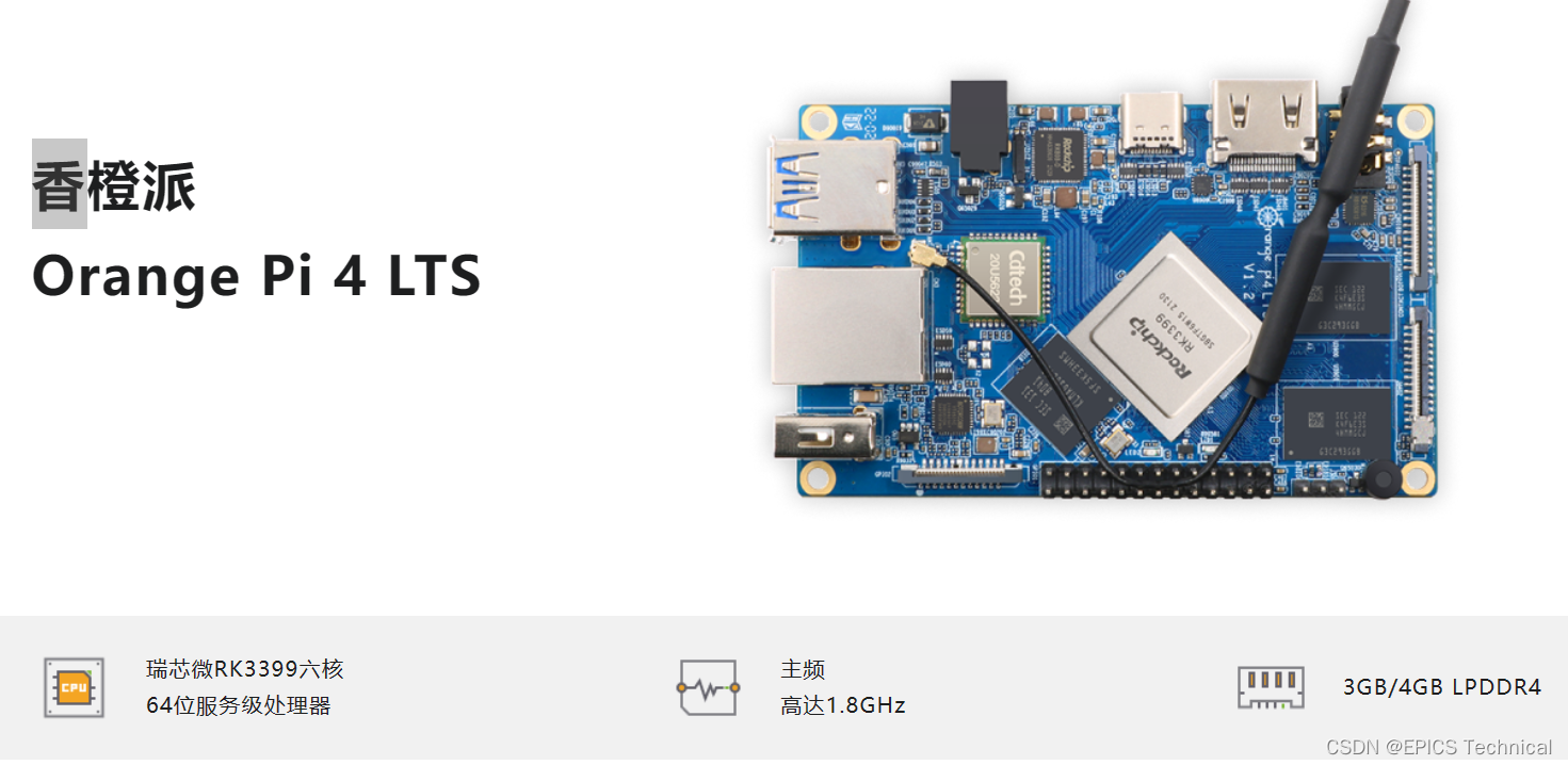
在本例中使用到的硬件是:

在程序中需要厂家提供的wringPi库,才能通过C语言库函数调用实现对其GPIO的控制。
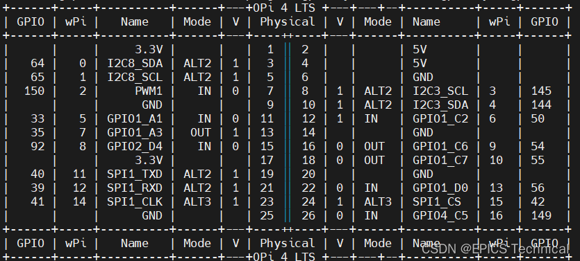
以下是这个单板机GPIO的管脚对应关系,本程序中用到的wPi编号是9和10:

本IOC应用程序,仅需要需要base和asyn模块,在configure/RELEASSE文件中指定:
SUPPORT = /usr/local/EPICS/synApps/support
ASYN = ${SUPPORT}/asyn

EPICS_BASE = /usr/local/EPICS/base
?以下是cpp源代码,它继承了asynPortDriver类,并且重写了其writeUInt32Digital方法,用于在指定GPIO管脚上,设置电平状态:
# drvgpioasyn.cpp
#include <iocsh.h>
#include <epicsThread.h>
#include <asynPortDriver.h>
#include <wiringPi.h>

#include <epicsExport.h>

static const char *driverName = "GPIOAsynDriver";

#define digitalOutputString       "DIGITAL_OUTPUT"

#define NUM_IO_BITS     2   // Number of digital I/O bits to USE

class GPIOAsynDriverOut : public asynPortDriver {
public:
  GPIOAsynDriverOut(const char *portName);

  /* These are the methods that we override from asynPortDriver */
  virtual asynStatus writeUInt32Digital(asynUser *pasynUser, epicsUInt32 value, epicsUInt32 mask);
  virtual void report(FILE *fp, int details);

protected:
  // Analog output parameters
  int digitalOutput_;
  #define FIRST_GPIOOUT_PARAM  digitalOutput_
  #define LAST_GPIOOUT_PARAM digitalOutput_
private:

  int gpio[2];
  void init_GPIO_Out();
  asynStatus setGPIO(int index, int val);
};

#define NUM_PARAMS ((int)(&LAST_GPIOOUT_PARAM - &FIRST_GPIOOUT_PARAM + 1))

GPIOAsynDriverOut::GPIOAsynDriverOut(const char *portName)
  : asynPortDriver(portName, 1 , NUM_PARAMS,
      asynUInt32DigitalMask | asynDrvUserMask,  // Interfaces that we implement
                      asynUInt32DigitalMask,                    // Interfaces that do callbacks
      ASYN_MULTIDEVICE | ASYN_CANBLOCK, 1, /* ASYN_CANBLOCK=1, ASYN_MULTIDEVICE=1, autoConnect=1 */
      0, 0) /* Default priority and stack size */
{
  // Digital I/O parameters
  init_GPIO_Out();
  createParam(digitalOutputString,     asynParamUInt32Digital, &digitalOutput_);
}

asynStatus GPIOAsynDriverOut::writeUInt32Digital(asynUser *pasynUser, epicsUInt32 value, epicsUInt32 mask)
{
  int function = pasynUser->reason;
  int status=0;
  int i;
  epicsUInt32 outValue=0, outMask;
  static const char *functionName = "writeUInt32Digital";


  setUIntDigitalParam(function, value, mask);
  if (function == digitalOutput_) {
    for (i=0, outMask=1; i<NUM_IO_BITS; i++, outMask = (outMask<<1)) {
      // Only write the value if the mask has this bit set
      outValue = ((value &outMask) == 0) ? 0 : 1;
      if ((mask & outMask ) != 0) {
        status = setGPIO(i, outValue);
      }
    }
  }

  if (status == 0) {
    asynPrint(pasynUser, ASYN_TRACEIO_DRIVER,
             "%s:%s, port %s, wrote outValue=0x%x, value=0x%x, mask=0x%x\n",
             driverName, functionName, this->portName, outValue, value, mask);
  } else {
    asynPrint(pasynUser, ASYN_TRACE_ERROR,
             "%s:%s, port %s, ERROR writing outValue=0x%x, value=0x%x, mask=0x%x,  status=%d\n",
             driverName, functionName, this->portName, outValue, value, mask, status);
  }
  return (status==0) ? asynSuccess : asynError;
}

void GPIOAsynDriverOut::init_GPIO_Out()
{
    int i;
    this->gpio[0] = 9;
    this->gpio[1] = 10;

    wiringPiSetup();
    for (i = 0; i < NUM_IO_BITS ; i++){
        pinMode(this->gpio[i], OUTPUT);
        digitalWrite(this->gpio[i], 0);
    }
}

asynStatus GPIOAsynDriverOut::setGPIO(int index, int val)
{
    digitalWrite(this->gpio[index], val);

    return asynSuccess;
}

void GPIOAsynDriverOut::report(FILE *fp, int details)
{

  fprintf(fp, "  Port: %s,GPIO %d - %d\n", this->portName, this->gpio[0], this->gpio[1]);

  asynPortDriver::report(fp, details);
}

extern "C" int GPIOAsynDriverOutConfig(const char *portName)
{
  GPIOAsynDriverOut *pGPIOAsynDriverOut = new GPIOAsynDriverOut(portName);
  pGPIOAsynDriverOut = NULL;
  return(asynSuccess);
}


static const iocshArg configArg0 = { "Port name",      iocshArgString};
static const iocshArg * const configArgs[] = {&configArg0,};
static const iocshFuncDef configFuncDef = {"GPIOAsynDriverOutConfig", 1, configArgs};
static void configCallFunc(const iocshArgBuf *args)
{
  GPIOAsynDriverOutConfig(args[0].sval);
}

void drvGPIOAsynDriverOutRegister(void)
{
  iocshRegister(&configFuncDef,configCallFunc);
}

extern "C" {
 epicsExportRegistrar(drvGPIOAsynDriverOutRegister);
}
编写一个数据库定义文件:
# drvgpioasyn.dbd
registrar(drvGPIOAsynDriverOutRegister)
在同级目录下的Makefile中指定需要的数据库定义文件,库文件以及源文件:
TOP=../..

include $(TOP)/configure/CONFIG
#----------------------------------------
#  ADD MACRO DEFINITIONS AFTER THIS LINE
#=============================

#=============================
# Build the IOC application

PROD_IOC = gpioasyn
# gpioasyn.dbd will be created and installed
DBD += gpioasyn.dbd

# gpioasyn.dbd will be made up from these files:
gpioasyn_DBD += base.dbd
gpioasyn_DBD += asyn.dbd
gpioasyn_DBD += drvgpioasyn.dbd

# Include dbd files from all support applications:
#gpioasyn_DBD += xxx.dbd

# Add all the support libraries needed by this IOC
gpioasyn_LIBS += asyn
gpioasyn_LIBS +=  wiringPi
wiringPi_DIR = /usr/lib


gpioasyn_SRCS += drvgpioasyn.cpp
# gpioasyn_registerRecordDeviceDriver.cpp derives from gpioasyn.dbd
gpioasyn_SRCS += gpioasyn_registerRecordDeviceDriver.cpp

# Build the main IOC entry point on workstation OSs.
gpioasyn_SRCS_DEFAULT += gpioasynMain.cpp
gpioasyn_SRCS_vxWorks += -nil-

# Add support from base/src/vxWorks if needed
#gpioasyn_OBJS_vxWorks += $(EPICS_BASE_BIN)/vxComLibrary

# Finally link to the EPICS Base libraries
gpioasyn_LIBS += $(EPICS_BASE_IOC_LIBS)

#===========================

include $(TOP)/configure/RULES
在Db/目录下,定义数据库模板文件digitalout.template,在此仅定义了一个数字量输出记录bo,用于写GPIO管脚:
record(bo, "$(P)$(R)")
{
    field(PINI, "$(PINI=YES)")
    field(DESC, "$(DESC=)")
    field(DTYP, "asynUInt32Digital")
    field(OUT,  "@asynMask($(PORT),$(ADDR),$(MASK))DIGITAL_OUTPUT")
    field(ZNAM, "$(ZNAM=Low)")
    field(ZSV,  "$(ZSV=NO_ALARM)")
    field(ONAM, "$(ONAM=High)")
    field(OSV,  "$(OSV=NO_ALARM)")
}
将这个模板文件添加到同级的Makefile文件中。
返回这个IOC的顶层目录,执行make,编译整个项目。
进入启动目录cd iocBoot/iocgpioasyn/,编辑以下文件:
1)?digitalout.substitutions
file "$(TOP)/db/digitalout.template"
{
pattern
{ R,   MASK,  ADDR}
{Bo1,  0x01,     0}
{Bo2,  0x02,     0}
}
2) st.cmd:
orangepi@orangepi4-lts:/usr/local/EPICS/program/gpioasyn/iocBoot/iocgpioasyn$ cat st.cmd
#!../../bin/linux-aarch64/gpioasyn

#- You may have to change gpioasyn to something else
#- everywhere it appears in this file

< envPaths

cd "${TOP}"

## Register all support components
dbLoadDatabase "dbd/gpioasyn.dbd"
gpioasyn_registerRecordDeviceDriver pdbbase

GPIOAsynDriverOutConfig("GPIO")
cd "${TOP}/iocBoot/${IOC}"
dbLoadTemplate("digitalout.substitutions","P=TEST:,PORT=GPIO,ADDR=0,TIMEOUT=1")
iocInit
启动程序,进行测试:
root@orangepi4-lts:/usr/local/EPICS/program/gpioasyn/iocBoot/iocgpioasyn# ../../bin/linux-aarch64/gpioasyn st.cmd
#!../../bin/linux-aarch64/gpioasyn
< envPaths
epicsEnvSet("IOC","iocgpioasyn")
epicsEnvSet("TOP","/usr/local/EPICS/program/gpioasyn")
epicsEnvSet("SUPPORT","/usr/local/EPICS/synApps/support")
epicsEnvSet("EPICS_BASE","/usr/local/EPICS/base")
cd "/usr/local/EPICS/program/gpioasyn"
## Register all support components
dbLoadDatabase "dbd/gpioasyn.dbd"
gpioasyn_registerRecordDeviceDriver pdbbase
## Load record instances
#dbLoadRecords("db/gpioasyn.db","user=orangepi")
GPIOAsynDriverOutConfig("GPIO")
cd "/usr/local/EPICS/program/gpioasyn/iocBoot/iocgpioasyn"
dbLoadTemplate("digitalout.substitutions","P=TEST:,PORT=GPIO,ADDR=0,TIMEOUT=1")
iocInit
Starting iocInit
############################################################################
## EPICS R7.0.7
## Rev. 2023-06-25T15:48+0000
## Rev. Date build date/time:
############################################################################
iocRun: All initialization complete
## Start any sequence programs
#seq sncxxx,"user=orangepi"
epics> dbl
TEST:Bo1
TEST:Bo2
用caput对IOC中加载的两个bo记录进行写1和写0,可以测量到GPIO对应管脚上电平的变化。
文章来源:https://blog.csdn.net/yuyuyuliang00/article/details/135030361
本文来自互联网用户投稿,该文观点仅代表作者本人,不代表本站立场。本站仅提供信息存储空间服务,不拥有所有权,不承担相关法律责任。 如若内容造成侵权/违法违规/事实不符,请联系我的编程经验分享网邮箱:chenni525@qq.com进行投诉反馈,一经查实,立即删除!
本文来自互联网用户投稿,该文观点仅代表作者本人,不代表本站立场。本站仅提供信息存储空间服务,不拥有所有权,不承担相关法律责任。 如若内容造成侵权/违法违规/事实不符,请联系我的编程经验分享网邮箱:chenni525@qq.com进行投诉反馈,一经查实,立即删除!
最新文章
- Python教程
- 深入理解 MySQL 中的 HAVING 关键字和聚合函数
- Qt之QChar编码(1)
- MyBatis入门基础篇
- 用Python脚本实现FFmpeg批量转换
- Java远程医疗会诊管理系统(源码+开题)
- vue3虚拟dom和diff算法实现(模仿源码)
- docker:安装docker项目的问题记录
- 华为mstp、vrrp、ospf、isis、bgp等综合一起排错
- 兼容M1~M3芯片?SPSS 27 For Mac版本?软件安装包下载 安装教程步骤?苹果电脑MAC系统 支持14 Sonoma
- 婚庆小程序集成多商家管理以及总后台管理不再需要电脑一个小程序解决所有管理
- 工程振弦采集仪监测技术的发展现状与展望
- pytest教程-6-skip跳过测试用例
- pytest学习和使用-pytest如何进行分布式测试?(pytest-xdist)
- 【算法练习】leetcode算法题合集之栈和队列篇