主动IRS(Active IRS)模型总结
文章目录
active IRS 与 passive IRS模型的区别
A Framework for Transmission Design for Active RIS-Aided Communication with Partial CSI
2023.5 TWC
https://ieeexplore.ieee.org/abstract/document/10134546
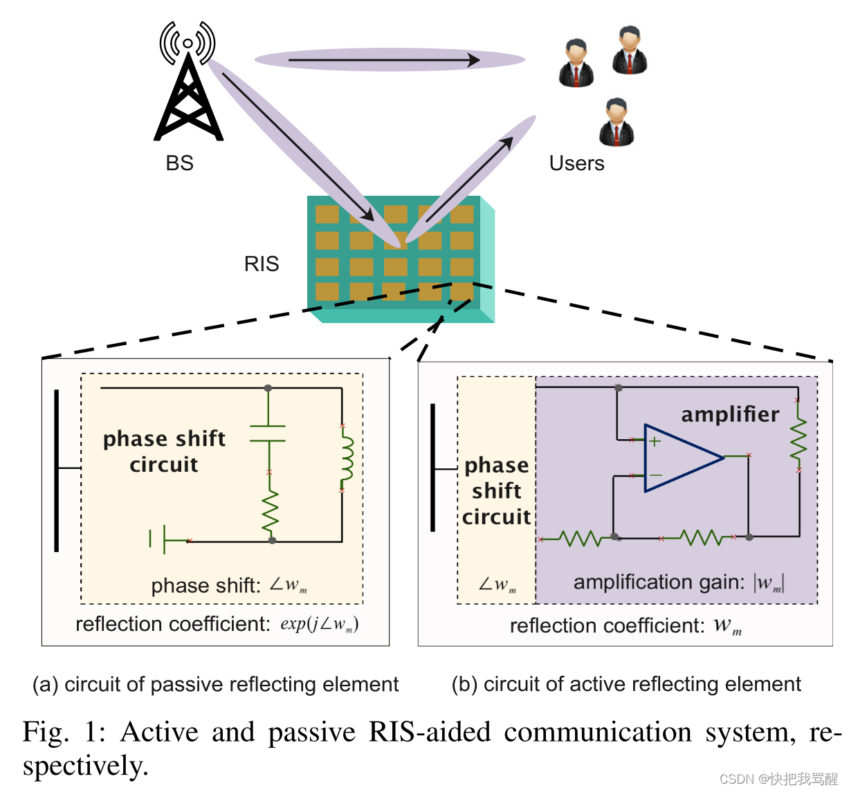
As shown in Fig. 1, we consider an RIS-aided downlink multiple-input single-output (MISO) system, where an N \mathrm{N} N antenna BS communicates with K K K single-antenna users. The RIS is assumed to be equipped with M M M reflecting elements, and its reflection coefficient matrix is given by Λ w = Diag ? ( w 1 , ? ? , w M ) ∈ C M × M \boldsymbol{\Lambda}_{\mathbf{w}}=\operatorname{Diag}\left(w_{1}, \cdots, w_{M}\right) \in \mathbb{C}^{M \times M} Λw?=Diag(w1?,?,wM?)∈CM×M. Here, ∠ w m \angle w_{m} ∠wm? and ∣ w m ∣ \left|w_{m}\right| ∣wm?∣ denote the phase shift and the reflection gain of the m m m -th RIS element, respectively. For passive RISs, each RIS element comprises an impedance adjustable circuit to vary the phase shift [19]. Thus, passive RISs are capable of reflecting the incident signal 2 ^{2} 2 without consuming direct-current (DC) power, which leads to a reflection gain of ∣ w m ∣ 2 = 1 \left|w_{m}\right|^{2}=1 ∣wm?∣2=1 and negligible thermal noise. However, the multiplicative fading effect results in a weak received signal power for the passive RIS reflection link. To address this issue, the authors of [9] and [10] proposed a new active RIS architecture, where each active RIS element includes an active reflection-type amplifier to also amplify the incident signals. Therefore, the corresponding reflection gain is given by 1 ≤ ∣ w m ∣ 2 ≤ a max ? 1 \leq\left|w_{m}\right|^{2} \leq a_{\max } 1≤∣wm?∣2≤amax? , where a max ? a_{\max } amax? is the maximum amplification gain.
The BS transmits K K K data symbols collected in vector s = [ s 1 , ? ? , s K ] T ∈ C K × 1 \mathbf{s}=\left[s_{1}, \cdots, s_{K}\right]^{\mathrm{T}} \in \mathbb{C}^{K \times 1} s=[s1?,?,sK?]T∈CK×1 to the users by applying precoder matrix F = [ f 1 , ? ? , f K ] ∈ C N × K \mathbf{F}=\left[\mathbf{f}_{1}, \cdots, \mathbf{f}_{K}\right] \in \mathbb{C}^{N \times K} F=[f1?,?,fK?]∈CN×K . Assuming independent complex Gaussian signals with E [ s s H ] = I N \mathbb{E}\left[\mathbf{s s}^{\mathrm{H}}\right]=\mathbf{I}_{N} E[ssH]=IN? , the BS transmit power is given by E { ∥ F s ∥ 2 2 } = ∥ F ∥ F 2 ≤ P N \mathbb{E}\left\{\|\mathbf{F s}\|_{2}^{2}\right\}=\|\mathbf{F}\|_{F}^{2} \leq P_{N} E{∥Fs∥22?}=∥F∥F2?≤PN? , where P N P_{N} PN? is the BS transmit power budget. Denote by H d r ∈ C M × N \mathbf{H}_{\mathrm{dr}} \in \mathbb{C}^{M \times N} Hdr?∈CM×N the channel from the BS to the RIS, and by h k ∈ C N × 1 \mathbf{h}_{k} \in \mathbb{C}^{N \times 1} hk?∈CN×1 and h r , k ∈ C M × 1 \mathbf{h}_{\mathrm{r}, k} \in \mathbb{C}^{M \times 1} hr,k?∈CM×1 the channels from user k k k to the BS and to the RIS, respectively. Then, the signal received by user k k k is given by
y k = h k H F s + h r , k H Λ w ( H d r F s + z ) + n k = ( h k H + h r , k H Λ w H d r ) F s + h r , k H Λ w z + n k , \begin{aligned} y_{k} & =\mathbf{h}_{k}^{\mathrm{H}} \mathbf{F} \mathbf{s}+\mathbf{h}_{\mathrm{r}, k}^{\mathrm{H}} \boldsymbol{\Lambda}_{\mathbf{w}}\left(\mathbf{H}_{\mathrm{dr}} \mathbf{F} \mathbf{s}+\mathbf{z}\right)+n_{k} \\ & =\left(\mathbf{h}_{k}^{\mathrm{H}}+\mathbf{h}_{\mathrm{r}, k}^{\mathrm{H}} \boldsymbol{\Lambda}_{\mathbf{w}} \mathbf{H}_{\mathrm{dr}}\right) \mathbf{F} \mathbf{s}+\mathbf{h}_{\mathrm{r}, k}^{\mathrm{H}} \boldsymbol{\Lambda}_{\mathbf{w}} \mathbf{z}+n_{k}, \end{aligned} yk??=hkH?Fs+hr,kH?Λw?(Hdr?Fs+z)+nk?=(hkH?+hr,kH?Λw?Hdr?)Fs+hr,kH?Λw?z+nk?,?
where n k n_{k} nk? and z \mathbf{z} z are the zero-mean additive white Gaussian noise (AWGN) at the user and the RIS, respectively, which follow distributions n k ~ CN ? ( 0 , σ k 2 ) n_{k} \sim \operatorname{CN}\left(0, \sigma_{k}^{2}\right) nk?~CN(0,σk2?) and z ~ CN ? ( 0 , σ z 2 I M ) \mathbf{z} \sim \operatorname{CN}\left(\mathbf{0}, \sigma_{z}^{2} \mathbf{I}_{M}\right) z~CN(0,σz2?IM?) with noise powers σ k 2 \sigma_{k}^{2} σk2? and σ z 2 \sigma_{z}^{2} σz2? , respectively. Notice that the thermal noise z \mathbf{z} z , which can be ignored in passive RIS-aided systems, has to be considered in active RIS-aided systems because of the amplification. The transmit power of the active RIS is given by
E { ∥ Λ w ( H d r F s + z ) ∥ 2 2 } = ∥ Λ w H d r F ∥ F 2 + ∥ w ∥ 2 2 σ z 2 , \mathbb{E}\left\{\left\|\boldsymbol{\Lambda}_{\mathbf{w}}\left(\mathbf{H}_{\mathrm{dr}} \mathbf{F} \mathbf{s}+\mathbf{z}\right)\right\|_{2}^{2}\right\}=\left\|\boldsymbol{\Lambda}_{\mathbf{w}} \mathbf{H}_{\mathrm{dr}} \mathbf{F}\right\|_{F}^{2}+\|\mathbf{w}\|_{2}^{2} \sigma_{z}^{2}, E{∥Λw?(Hdr?Fs+z)∥22?}=∥Λw?Hdr?F∥F2?+∥w∥22?σz2?,
where w = [ w 1 , ? ? , w M ] H \mathbf{w}=\left[w_{1}, \cdots, w_{M}\right]^{\mathrm{H}} w=[w1?,?,wM?]H . Furthermore, the achievable rate of user k k k is given by
R k ( F , w ) = log ? 2 ( 1 + 1 I N k ∣ ( h k H + h r , k H Λ w H d r ) f k ∣ 2 ) R_{k}(\mathbf{F}, \mathbf{w})=\log _{2}\left(1+\frac{1}{\mathrm{IN}_{k}}\left|\left(\mathbf{h}_{k}^{\mathrm{H}}+\mathbf{h}_{\mathrm{r}, k}^{\mathrm{H}} \mathbf{\Lambda}_{\mathbf{w}} \mathbf{H}_{\mathrm{dr}}\right) \mathbf{f}_{k}\right|^{2}\right) Rk?(F,w)=log2?(1+INk?1? ?(hkH?+hr,kH?Λw?Hdr?)fk? ?2)
where I N k = ∑ i = 1 , i ≠ k K ∣ ( h k H + h r , k H Λ w H d r ) f i ∣ 2 + σ k 2 + ∥ h r , k H Λ w ∥ 2 2 σ z 2 \mathrm{IN}_{k}=\sum_{i=1, i \neq k}^{K}\left|\left(\mathbf{h}_{k}^{\mathrm{H}}+\mathbf{h}_{\mathrm{r}, k}^{\mathrm{H}} \boldsymbol{\Lambda}_{\mathbf{w}} \mathbf{H}_{\mathrm{dr}}\right) \mathbf{f}_{i}\right|^{2}+\sigma_{k}^{2}+ \left\|\mathbf{h}_{\mathrm{r}, k}^{\mathrm{H}} \boldsymbol{\Lambda}_{\mathbf{w}}\right\|_{2}^{2} \sigma_{z}^{2} INk?=∑i=1,i=kK? ?(hkH?+hr,kH?Λw?Hdr?)fi? ?2+σk2?+ ?hr,kH?Λw? ?22?σz2? .
Hybrid active and passive IRS
统计信道状态信息和worst case信道状态信息有何区别。
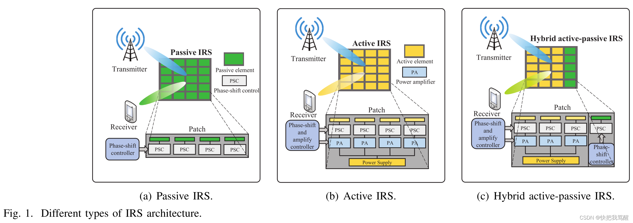
为了解决上述问题,最近提出了一种新型 IRS,称为主动 IRS(参见[20]-[24])。具体地,有源IRS包括多个有源反射元件,每个有源反射元件配备有有源负载(或称为负电阻),例如隧道二极管和负阻抗转换器。如图 1(b)所示,每个有源负载都连接到一个附加电源以进行信号放大[25]、[26]。因此,有源 IRS 不仅能够像无源 IRS 一样实现可调节的相移,而且还允许在全双工模式下对入射信号进行幅度放大(即大于 1),尽管其硬件和能源成本比无源 IRS 稍高一些 [21]。另一方面,与将射频链连接到天线的有源中继相比,有源 IRS 不需要昂贵且耗电的射频链组件 [27]。最近的文献研究了主动式 IRS 和被动式 IRS 之间的性能比较。例如,给定主动 IRS 位置和功率预算,事实证明,主动 IRS 可以比被动 IRS 实现更高的频谱效率 [21]、[28]、能源效率 [24] 和可靠性 [29]。此外,[23] 中的作者进一步优化了被动和主动 IRS 辅助系统的 IRS 放置,以实现速率最大化。结果表明,当反射元件数量较大和/或有源元件放大功率较小时,无源 IRS 通过各自的优化放置实现了比有源 IRS 更高的速率性能。此外,[22]中的作者考虑了无源和有源IRS辅助系统相同的功率预算约束,其中在有源IRS的情况下,同时考虑了基站(BS)的发射功率和有源IRS的放大功率。结果表明,只有当反射元件的数量很少和/或有源IRS的放大功率足够大时,有源IRS才优于无源IRS。
总而言之,现有的 IRS 工作表明,被动 IRS 和主动 IRS 具有互补优势。具体来说,无源 IRS 比有源 IRS 具有更高的渐近波束形成增益(即 O(N2) 与 O(N)),因此当反射元件数量 N 较大时更有吸引力 [21]、[23]。相比之下,有源 IRS 提供额外的功率放大增益,当 N 相对较小时,这会导致比无源 IRS 高得多的信噪比 (SNR) [25]、[30]、[31]。此外,主动IRS通常比被动IRS产生更高的成本和功耗。因此,这些表明,给定IRS部署成本的总预算(或者等效地要部署的有源/无源反射元件的数量),仅具有无源或有源元件的传统IRS架构可能无法实现最佳通信性能。
受上述启发,我们在本文中提出了一种新的混合主动-被动IRS2架构,如图1(c)所示,以实现被动和主动IRS的优点,进一步提高比单独使用主动或被动IRS的性能。具体来说,混合IRS由两个位于同一位置的子表面组成,每个子表面分别由一定数量的无源和有源反射元件组成。
为了实现最佳性能,我们在给定的部署预算下设计了混合IRS的有源与无源反射元件分配,以最佳平衡有源IRS独特的功率放大增益和无源IRS比有源IRS更高的波束成形增益之间的权衡。为此,我们考虑如图 2 所示的混合主动-被动 IRS 辅助多用户通信系统,其中 BS 向用户集群传输独立数据。混合IRS被正确地部署在该用户集群的边缘,以在不同的时隙为其半空间反射区域中的用户提供服务。我们根据实际模型考虑混合 IRS 的给定部署预算,以及每个有源和无源元件的不同成本,其中有源元件通常比无源元件产生更高的成本3。为了减少实时信道估计开销并避免频繁的 IRS 反射调整,我们考虑一种实用的方法,即仅基于统计信道状态信息(CSI)设计混合 IRS 波束成形,假设实际的莱斯衰落信道模型(即仅假设信道路径损耗参数和莱斯衰落因子已知),而不需要了解所有相关链路的瞬时 CSI。下面,我们总结了本文的主要贡献。
从已有passive IRS算法拓展到active IRS算法
不需要考虑原来的被动相位约束,需要新增加Active IRS的发射功率约束。
passive IRS可以视为Active IRS的特例
本文来自互联网用户投稿,该文观点仅代表作者本人,不代表本站立场。本站仅提供信息存储空间服务,不拥有所有权,不承担相关法律责任。 如若内容造成侵权/违法违规/事实不符,请联系我的编程经验分享网邮箱:chenni525@qq.com进行投诉反馈,一经查实,立即删除!
- Python教程
- 深入理解 MySQL 中的 HAVING 关键字和聚合函数
- Qt之QChar编码(1)
- MyBatis入门基础篇
- 用Python脚本实现FFmpeg批量转换
- 基于树种算法优化的Elman神经网络数据预测 - 附代码
- ABAP与HANA集成 2:ABAP调用HANA存储过程或SQL语句
- 比利时市场开发攻略,带你走进欧洲心脏
- 竞赛保研 基于深度学习的中文情感分类 - 卷积神经网络 情感分类 情感分析 情感识别 评论情感分类
- 连接器应用案例详解 | prodesign加速卡采用Samtec NovaRay? 极高密度阵列
- 【LeetCode】349. 两个数组的交集(简单)——代码随想录算法训练营Day06
- 基于SSM的高校疫情防控出入信息管理系统的设计与实现论文
- 公路站点加油
- 常见端口介绍
- 电子公章软件,怎么实现批量自动盖章?