DLPC6540简介--DLPC入门1
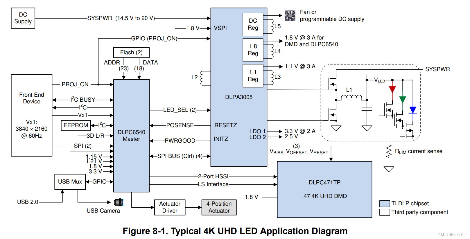
1. Application block diagram

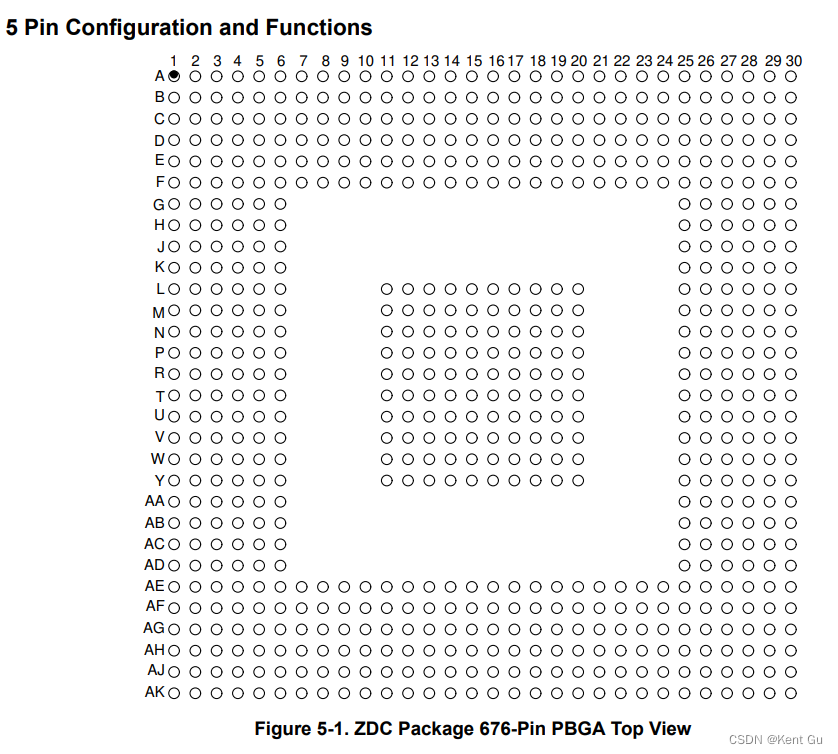
2. Component & Pin package

-
Signal definition
3.1, Initialization, Board Level Test and Debug: Pwr signal, Reset, JTAG, Test pin
3.2, Analog front end(not supported in DLPC6540)
3.2, V-by-one interface input data and control(HS video input): VX1_0~7_P/N, VX1_HOTPDN(RSD), VX1_LOCKN(RSD),
VX1_CM_CKREF0~3(RSD), VX1_CM_AMOUT0~3(RSD)
3.3, OpenLDI(FPD-LINK I)(not supported in DLPC6540)
3.4, Parallel Port input data and control(RSD)
3.5, DMD Reset and low speed inteface
3.6, DMD HSSI(high speed serial interface)
3.7, Program Memory Interface: PM_CSZ_0~2(Chip Select), PM_ADDR0_23, PM_WEZ(write enable), PM_OEW(output
enable), PM_BLSZ0~1(lower byte/upper byte),PM_DATA0~15
3.8, Peripheral Interface: I2C, SPI, UART, USB
3.9, GPIO:GPIO87~00
3.10, Clock and support:REFCLKA_I, REFCLKA_O(crystal A),REFCLKB_I,REFCLKB_O(crystal B),OCLKA
3.11, Power and Ground: 1.15V, 1.8V, 3.3V, 1.21V, -
Feature Description
4.1, Input source, Vx1
4.2, ?Processing delay
本文来自互联网用户投稿,该文观点仅代表作者本人,不代表本站立场。本站仅提供信息存储空间服务,不拥有所有权,不承担相关法律责任。 如若内容造成侵权/违法违规/事实不符,请联系我的编程经验分享网邮箱:chenni525@qq.com进行投诉反馈,一经查实,立即删除!
- Python教程
- 深入理解 MySQL 中的 HAVING 关键字和聚合函数
- Qt之QChar编码(1)
- MyBatis入门基础篇
- 用Python脚本实现FFmpeg批量转换
- Linux进程信号之初识信号
- 【java IO】|java NIO总结
- C# SqlSugar 数据库 T4模板
- JavaScript 中的闭包是什么?有哪些应用场景?
- LinkSLA智能运维 优化企业运维的利器
- 重生奇迹mu翅膀教程攻略
- 【设计模式之美】 SOLID 原则之四:接口隔离原则有哪三种应用?原则中的“接口”该如何理解?
- 记录每日LeetCode 72.编辑距离 Java实现
- gitgud.io+Sapphire注册账号教程
- 机器人自动打电话软件有哪些功能