RT-Thread Studio学习(十七)虚拟串口
发布时间:2024年01月20日
RT-Thread Studio学习(十七)虚拟串口
一、简介
本文将基于STM32F407VET芯片介绍如何在RT-Thread Studio开发环境下实现USB虚拟串口。
硬件及开发环境如下:
- OS WIN10
- STM32F407VET6
- STM32CubeMX v6.10.0
- STM32Cube MCU Package for STM32F4 Series v1.28.0
- RT-Thread Studio v2.2.7
- RT-Thread Source Code v5.0.2
- STM32F4 chip support packages v0.2.3
二、新建RT-Thread项目并使用外部时钟
打开RT-Thread Studio软件新建基于芯片的项目,并使用外部时钟系统,具体参见《RT-Thread Studio学习(一)新建工程》。
三、启用USB设备功能
- 打开USB设备驱动框架
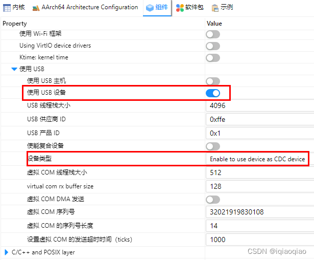
在RT-Thread Setting中借助图形化配置工具打开组件中的USB设备的驱动框架,设置设备类型为Enable to use device as CDC device,如下图所示:

- 定义USB相关的宏
在board.h文件中使能宏定义
#define BSP_USING_USBDEVICE
- 复制USB设备初始化函数
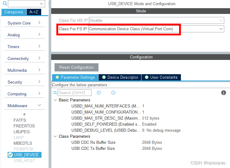
双击RT-Thread Studio工程中的cubemx.ioc文件,设置USB OTG


再重新生成STM32CubeMX代码,将.\cubemx\Src\usbd_conf.c中的函数HAL_PCD_MspInit复制到board.c的末尾。
void HAL_PCD_MspInit(PCD_HandleTypeDef* pcdHandle)
{
  GPIO_InitTypeDef GPIO_InitStruct = {0};
  if(pcdHandle->Instance==USB_OTG_FS)
  {
  /* USER CODE BEGIN USB_OTG_FS_MspInit 0 */

  /* USER CODE END USB_OTG_FS_MspInit 0 */

    __HAL_RCC_GPIOA_CLK_ENABLE();
    /**USB_OTG_FS GPIO Configuration
    PA11     ------> USB_OTG_FS_DM
    PA12     ------> USB_OTG_FS_DP
    */
    GPIO_InitStruct.Pin = GPIO_PIN_11|GPIO_PIN_12;
    GPIO_InitStruct.Mode = GPIO_MODE_AF_PP;
    GPIO_InitStruct.Pull = GPIO_NOPULL;
    GPIO_InitStruct.Speed = GPIO_SPEED_FREQ_VERY_HIGH;
    GPIO_InitStruct.Alternate = GPIO_AF10_OTG_FS;
    HAL_GPIO_Init(GPIOA, &GPIO_InitStruct);

    /* Peripheral clock enable */
    __HAL_RCC_USB_OTG_FS_CLK_ENABLE();

    /* Peripheral interrupt init */
    HAL_NVIC_SetPriority(OTG_FS_IRQn, 0, 0);
    HAL_NVIC_EnableIRQ(OTG_FS_IRQn);
  /* USER CODE BEGIN USB_OTG_FS_MspInit 1 */

  /* USER CODE END USB_OTG_FS_MspInit 1 */
  }
}
- 定义.\cubemx\Inc\stm32f4xx_hal_conf.h中的相关宏
#define HAL_PCD_MODULE_ENABLED
四、测试
修改main.c的代码,主要添加的代码如下:
/* 用于接收消息的信号量 */
static struct rt_semaphore rx_sem;
static rt_device_t serial;

//

/* 接收数据回调函数 */
static rt_err_t uart_input(rt_device_t dev, rt_size_t size)
{
    /* 串口接收到数据后产生中断,调用此回调函数,然后发送接收信号量 */
    rt_sem_release(&rx_sem);

    return RT_EOK;
}

static void serial_thread_entry(void *parameter)
{
    char ch;
    LOG_D("uart_rx_thread_entry runing..\n");
    while (1)
    {
        /* 从串口读取一个字节的数据,没有读取到则等待接收信号量 */
        while (rt_device_read(serial, -1, &ch, 1) != 1)
        {
            /* 阻塞等待接收信号量,等到信号量后再次读取数据 */
            rt_sem_take(&rx_sem, RT_WAITING_FOREVER);
        }

        rt_kprintf("%c",ch);
        /* 读取到的数据通过串口错位输出 */
        rt_device_write(serial, 0, &ch, 1);
    }
}

static int serial_init()
{
    rt_err_t ret = RT_EOK;

    /* 查找设备 */
    serial = rt_device_find("vcom");
    if (serial  == RT_NULL)
    {
        rt_kprintf("can't find vcom device!\n");
        return RT_ERROR;
    }
    ret = rt_device_init(serial);
    if (serial  == RT_NULL)
    {
        rt_kprintf("can't initialize vcom device!\n");
        return RT_ERROR;
    }

    /* 打开设备,可读写,中断接收 */
    ret = rt_device_open(serial, RT_DEVICE_FLAG_RDWR | RT_DEVICE_FLAG_INT_RX);

    //初始化信号量
    rt_sem_init(&rx_sem, "rx_sem", 0, RT_IPC_FLAG_FIFO);

    // 设置接收回调函数
    rt_device_set_rx_indicate(serial, uart_input);

    rt_thread_t thread = rt_thread_create("serial", serial_thread_entry, RT_NULL, 1024, 25, 10);
    if (thread == RT_NULL)
    {
        LOG_E("rt_thread_create failed...\n");
    }
    rt_thread_startup(thread);
    return RT_EOK;
}
在主函数main中,添加
char buf2[64];
for(int i=0; i<64; i++)
    buf2[i] = i;
rt_device_write(serial, 0, buf2, 64);
rt_thread_mdelay(1);
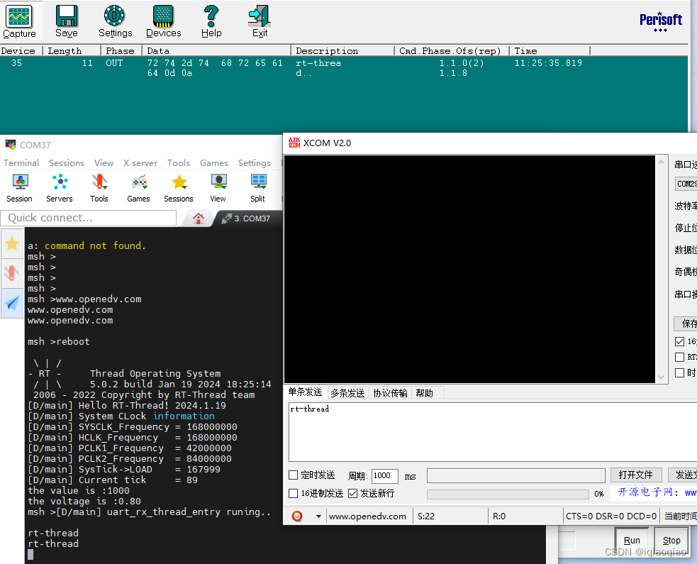
编译后下载,发现在串口调试助手中,能打开CDC串口并发送数据。发送数据不但能通过Bus Hound软件抓包到,而且STM32通过USART1调试口回传至PC,但调试助手的CDC串口却收不到任何数据。

原因在于STM32虚拟的串口为USB设备,PC端需主动“索取”才能获得rt_device_write发出的数据。
后面在PC端编写了python串口读取程序,才能接收到rt_device_write发出的数据,并且数据速率非常高,达到数百KBps。
文章来源:https://blog.csdn.net/iqiaoqiao/article/details/135708374
本文来自互联网用户投稿,该文观点仅代表作者本人,不代表本站立场。本站仅提供信息存储空间服务,不拥有所有权,不承担相关法律责任。 如若内容造成侵权/违法违规/事实不符,请联系我的编程经验分享网邮箱:chenni525@qq.com进行投诉反馈,一经查实,立即删除!
本文来自互联网用户投稿,该文观点仅代表作者本人,不代表本站立场。本站仅提供信息存储空间服务,不拥有所有权,不承担相关法律责任。 如若内容造成侵权/违法违规/事实不符,请联系我的编程经验分享网邮箱:chenni525@qq.com进行投诉反馈,一经查实,立即删除!
最新文章
- Python教程
- 深入理解 MySQL 中的 HAVING 关键字和聚合函数
- Qt之QChar编码(1)
- MyBatis入门基础篇
- 用Python脚本实现FFmpeg批量转换
- 音频I2S
- 基于springboot的特产销售系统-协同过滤算法【数据库设计、论文、毕设源码、开题报告】
- Hive实战:统计总分与平均分
- 深度学习笔记(二)——Tensorflow环境的安装
- Leveraging Unlabeled Data for Crowd Counting by Learning to Rank
- 商业印刷市场分析:预计2029年将达到53004亿元
- 16-Kafka Broker
- 分解质因数算法总结
- 等待队列头实现非阻塞 IO(NIO)
- 一个可搜索的表格