【静态路由】综合实验
静态路由综合实验
一、实验拓扑图及组网要求
实验拓扑图
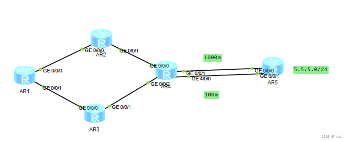
组网要求
- 除R5的环回地址以固定外,整个其他所有的网段基于192.168.1./24进行合理的IP地址划分
- R1-R4每天路由器存在两个环回接口,用于模拟连接pc的网段;地址也在192.168.1.0/24这个网络范围内
- R1-R4上不能直接编写到达5.5.5./24的静态路由,但依然可以访问
- 全网可达,尽量减少每台路由器,路由表条目的数量,避免环路出现
- R4与R5间,正常1eeem链路通信,故障时自动改为100M
二、设计思路
1、划分IP,给设备配置IP地址
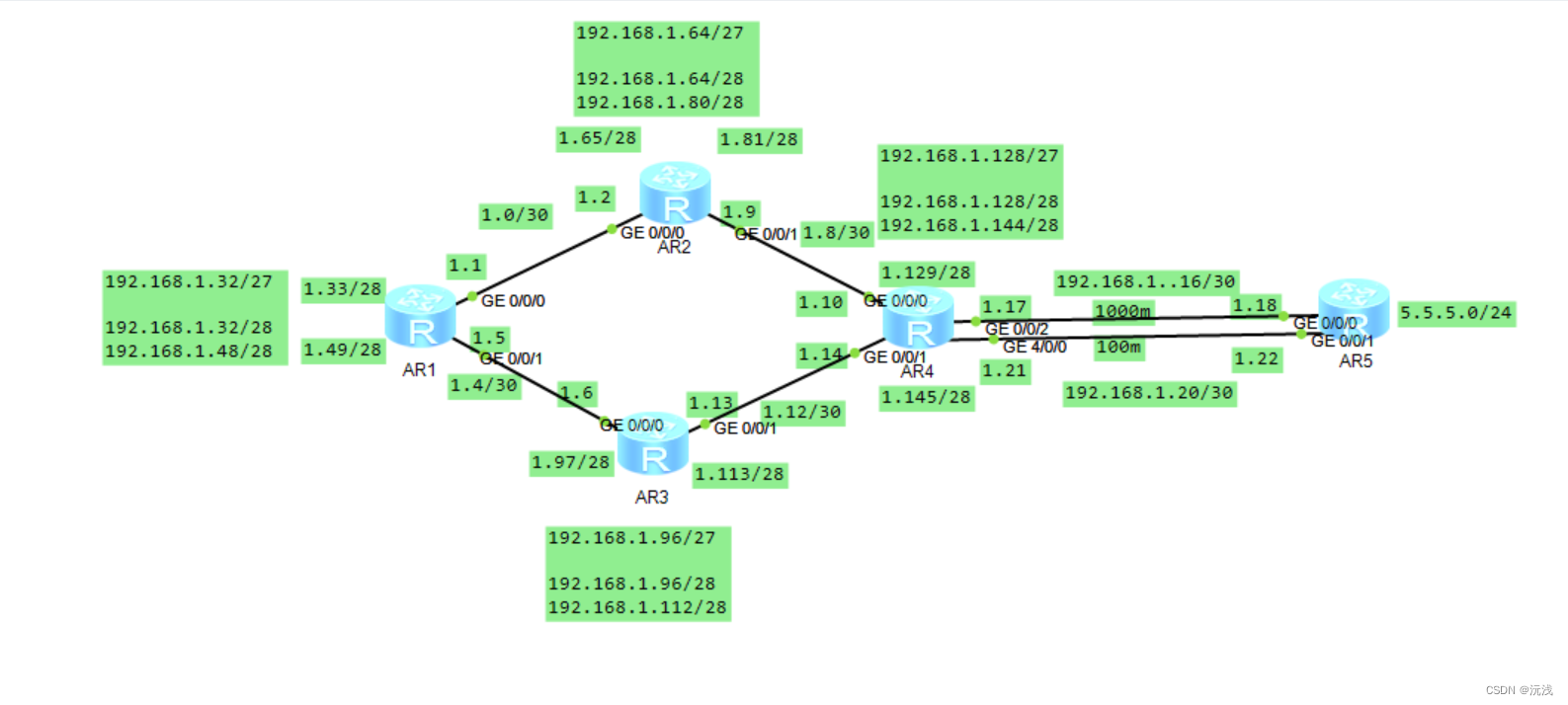
分析:观察拓扑结构将网络分为五大网段(骨干链路为一个大网段、其余除RE外的路由器的两个环回为一个大网段)
-
骨干链路网段192.168.1.0/27
192.168.1.0/30
192.168.1.4/30
192.168.1.12/30
192.168.1.20/30
192.168.1.8/30
192.168.1.16/30 -
192.168.1.32/27—RA环回
192.168.1.32/28----L0
192.168.1.48/28—L1 -
192.168.1.64/27—RB环回
192.168.1.64/28----L0
192.168.1.80/28-----L1 -
192.168.1.96/27—RD环回
192.168.1.96/28----L0
192.168.1.112/28----L1 -
192.168.1.128/27—RC环回
192.168.1.128/28—L0
192.168.1.144/28—L1
2、编写到达除了5.5.5.0/24之外的其他所有网段的静态路由
3、配置缺省路由,实现全网通
4、防环,减少路表数量
5、做备份,改变路由的优先级
6、测试,断掉1000M链路,测试数据能否走100M链路
最终ip地址分配如图:
三、实验配置
首先按照地址给每个路由器分配ip地址
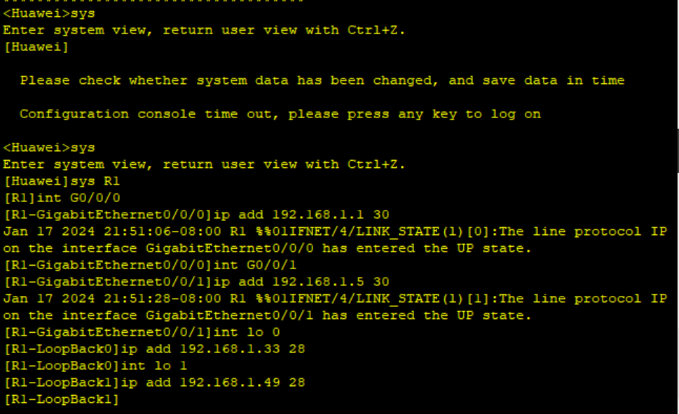
R1的静态路由配置:
<Huawei>sys
[Huawei]sysname R1
[R1]
[R1]int g0/0/0
[R1-GigabitEthernet0/0/0]ip add 192.168.1.1 30
[R1-GigabitEthernet0/0/0]int g0/0/1
[r1-GigabitEthernet0/0/1]ip add 192.168.1.5 30
[R1-GigabitEthernet0/0/1]int lo 0
[R1-LoopBack0]ip add 192.168.1.33 28
[R1-LoopBack0]int lo 1
[R1-LoopBack1]ip add 192.168.1.49 28
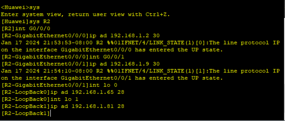
R2的静态路由配置:
<Huawei>sys
[Huawei]sysname R2
[R2]
[R2]int g0/0/0
[R2-GigabitEthernet0/0/0]ip ad 192.168.1.2 30
[R2-GigabitEthernet0/0/0]int g0/0/1
[R2-GigabitEthernet0/0/1]ip ad 192.168.1.9 30
[R2-GigabitEthernet0/0/1]int lo 0
[R2-LoopBack0]ip ad 192.168.1.65 28
[R2-LoopBack0]int lo1
[R2-LoopBack1]ip ad 192.168.1.81 28
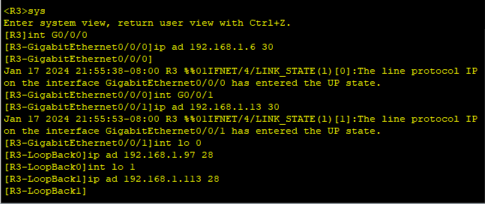
R3的静态路由配置:
<Huawei>sys
[Huawei]sysname R3
[R3]
[R3]int g0/0/0
[R3-GigabitEthernet0/0/0]ip ad 192.168.1.6 30
[R3-GigabitEthernet0/0/0]int g0/0/1
[R3-GigabitEthernet0/0/1]ip ad 192.168.1.13 30
[R3-GigabitEthernet0/0/1]int lo0
[R3-LoopBack0]ip ad 192.168.1.97 28
[R3-LoopBack0]int lo1
[R3-LoopBack1]ip ad 192.168.1.113 28
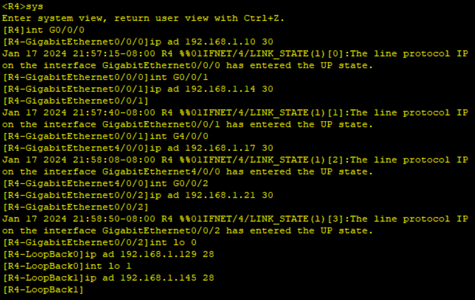
R4的静态路由配置:
<Huawei>sys
[Huawei]sysname R4
[R4]
[R4]int g0/0/0
[R4-GigabitEthernet0/0/0]ip ad 192.168.1.10 30
[R4-GigabitEthernet0/0/0]int g0/0/1
[R4-GigabitEthernet0/0/1]ip ad 192.168.1.14 30
[R4-GigabitEthernet0/0/1]int g4/0/0
[R4-GigabitEthernet4/0/0]ip ad 192.168.1.17 30
[R4-GigabitEthernet4/0/0]int g0/0/2
[R4-GigabitEthernet0/0/2]ip ad 192.168.1.21 30
[R4-GigabitEthernet0/0/2]int lo0
[R4-LoopBack0]ip ad 192.168.1.129 28
[R4-LoopBack0]int lo1
[R4-LoopBack1]ip ad 192.168.1.145 28
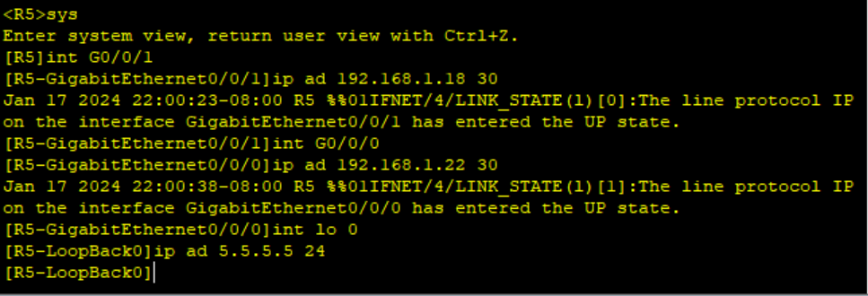
R5的静态路由配置:
<Huawei>sys
[Huawei]sysname R5
[R5]
[R5]int g0/0/1
[R5-GigabitEthernet0/0/1]ip add 192.168.1.18 30
[R5-GigabitEthernet0/0/1]int g0/0/0
[R5-GigabitEthernet0/0/0]ip add 192.168.1.22 30
[R5-GigabitEthernet0/0/0]int lo0
[R5-LoopBack0]ip ad 5.5.5.5 24
配置完成之后检查
display ip interface brief
进行路由配置
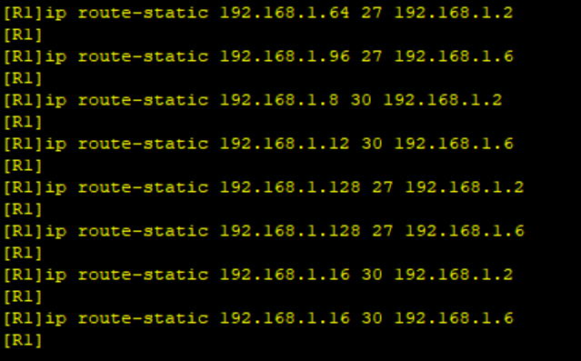
R1路由配置:
[R1]ip route-static 192.168.1.64 27 192.168.1.2
[R1]ip route-static 192.168.1.96 27 192.168.1.6
[R1]ip route-static 192.168.1.8 30 192.168.1.2
[R1]ip route-static 192.168.1.12 30 192.168.1.6
[R1]ip route-static 192.168.1.128 27 192.168.1.2
[R1]ip route-static 192.168.1.128 27 192.168.1.6
[R1]ip route-static 192.168.1.16 30 192.168.1.2
[R1]ip route-static 192.168.1.16 30 192.168.1.6
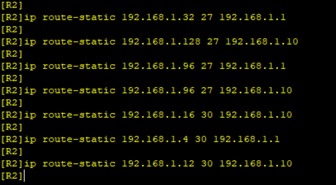
R2路由配置:
[R2]ip route-static 192.168.1.32 27 192.168.1.1
[R2]ip route-static 192.168.1.128 27 192.168.1.10
[R2]ip route-static 192.168.1.96 27 192.168.1.1
[R2]ip route-static 192.168.1.96 27 192.168.1.10
[R2]ip route-static 192.168.1.16 30 192.168.1.10
[R2]ip route-static 192.168.1.4 30 192.168.1.1
[R2]ip route-static 192.168.1.12 30 192.168.1.10
R3路由配置:
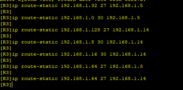
[R3]ip route-static 192.168.1.32 27 192.168.1.5
[R3]ip route-static 192.168.1.0 30 192.168.1.5
[R3]ip route-static 192.168.1.128 27 192.168.1.14
[R3]ip route-static 192.168.1.8 30 192.168.1.14
[R3]ip route-static 192.168.1.16 30 192.168.1.14
[R3]ip route-static 192.168.1.64 27 192.168.1.5
[R3]ip route-static 192.168.1.64 27 192.168.1.14
R4路由配置:
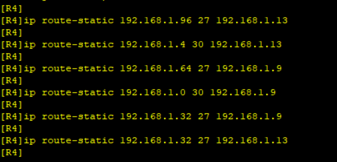
[R4]ip route-static 192.168.1.96 27 192.168.1.13
[R4]ip route-static 192.168.1.4 30 192.168.1.13
[R4]ip route-static 192.168.1.64 27 192.168.1.9
[R4]ip route-static 192.168.1.0 30 192.168.1.9
[R4]ip route-static 192.168.1.32 27 192.168.1.9
[R4]ip route-static 192.168.1.32 27 192.168.1.13
R5路由配置:
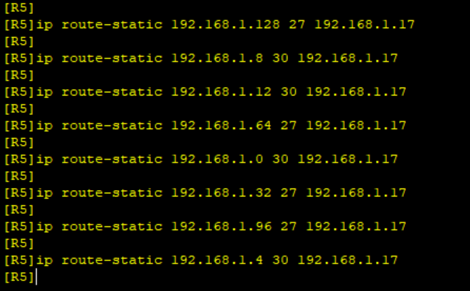
[R5]ip route-static 192.168.1.128 27 192.168.1.17
[R5]ip route-static 192.168.1.8 30 192.168.1.17
[R5]ip route-static 192.168.1.12 30 192.168.1.17
[R5]ip route-static 192.168.1.64 27 192.168.1.17
[R5]ip route-static 192.168.1.0 30 192.168.1.17
[R5]ip route-static 192.168.1.32 27 192.168.1.17
[R5]ip route-static 192.168.1.96 27 192.168.1.17
[R5]ip route-static 192.168.1.4 30 192.168.1.17
由于R1-R4不能直接编写到5.5.5.0/24的静态路由,也就是无法访问5.5.5.0网段,自然ping到5.5.5.5也ping不过去,若要让其能访问,于是我们给各个路由写上缺省地址。
R1的缺省地址:
[R1]ip route-static 0.0.0.0 0.0.0.0 192.168.1.2
[R1]ip route-static 0.0.0.0 0.0.0.0 192.168.1.6

R2的缺省地址:
[R2]ip route-static 0.0.0.0 0.0.0.0 192.168.1.10

R3的缺省地址:
[R3]ip route-static 0.0.0.0 0.0.0.0 192.168.1.14

R4的缺省地址:
[R4]ip route-static 0.0.0.0 0.0.0.0 192.168.1.18

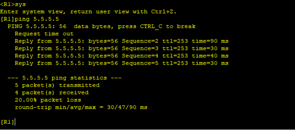
这个时候每个路由再去ping5.5.5.5就可以通啦!
此外,为了避免环路出现,还应该在每个路由添加空接口
R1
[R1]ip route-static 192.168.1.32 27 NULL 0
R2
[R2]ip route-static 192.168.1.64 27 NULL 0
R3
[R3]ip route-static 192.168.1.96 27 NULL 0
R4
[R4]ip route-static 192.168.1.128 27 NULL 0
要使R4与R5间,正常1000M链路通信,故障时自动改为100M,就要用到浮动静态路由,根据优先级的数值越小,优先级越高,将100M链路的优先级调整为61即可。
修改100M链路的优先级
[R5]ip route-static 192.16.1.0 255.255.255.252 192.168.1.21 preference 61
[R5]ip route-static 192.168.1.4 255.255.255.252 192.168.1.21 preference 61
[R5]ip route-static 192.168.1.8 255.255.255.252 192.168.1.21 preference 61
[R5]ip route-static 192.168.1.12 255.255.255.252 192.168.1.21 preference 61
[R5]ip route-static 192.168.1.32 255.255.255.252 192.168.1.21 preference 61
[R5]ip route-static 192.168.1.64 255.255.255.252 192.168.1.21 preference 61
[R5]ip route-static 192.168.1.96 255.255.255.252 192.168.1.21 preference 61
[R5]ip route-static 192.168.1.128 255.255.255.252 192.168.1.21 preference 61
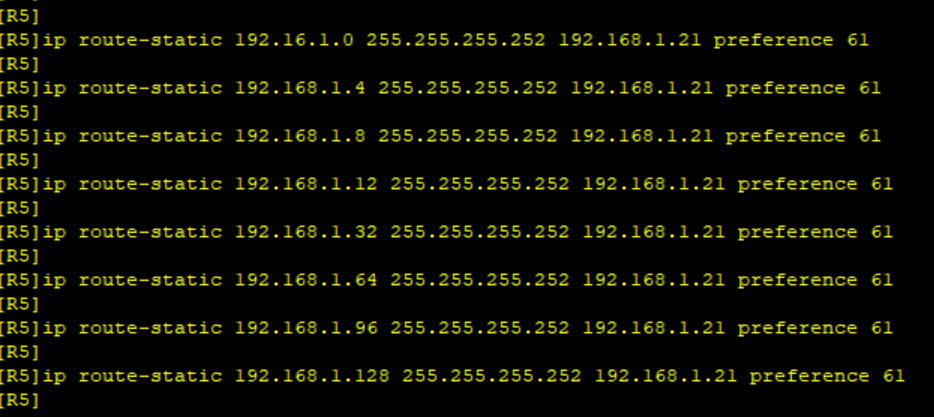
[R4]ip route-static 0.0.0.0 0 192.168.1.22 preference 61

接下来验证是否在故障时使用的是100M的链路,首先需将1000M链路断开
[R4]int g4/0/0
[R4-GigabitEthernet4/0/0]shutdown
[R5]int g0/0/1
[R5-GigabitEthernet0/0/1]shutdown
断开之后我们再去R4路由查看此时的路由表,就可以发现100M的接口已经在路由表上了
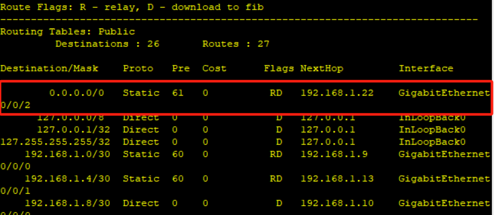 接下来我们再让R1ping5.5.5.5做个例子,看是否能ping过去
本文来自互联网用户投稿,该文观点仅代表作者本人,不代表本站立场。本站仅提供信息存储空间服务,不拥有所有权,不承担相关法律责任。 如若内容造成侵权/违法违规/事实不符,请联系我的编程经验分享网邮箱:chenni525@qq.com进行投诉反馈,一经查实,立即删除!
- Python教程
- 深入理解 MySQL 中的 HAVING 关键字和聚合函数
- Qt之QChar编码(1)
- MyBatis入门基础篇
- 用Python脚本实现FFmpeg批量转换
- 方法的定义以及方法的调用
- 高性能NVMe Host Controller IP
- C类期刊论文复现:基于共享储能电站的工业用户日前优化经济调度程序代码!
- 实战演练 | Navicat 中编辑器设置的配置
- 华为OD机试真题-中文分词模拟器-2023年OD统一考试(C卷)
- 2024阿里云服务器ECS实例全方位介绍_优缺点大全
- Redis快速入门
- JavaScript系列-函数调用之apply、call、bind
- Jenkins自动化构建和部署多模块服务
- 面试题目1