STM32入门—构建库函数
在前面我们已经能够点亮LED,参考这篇博文STM32入门第一步—点亮LED灯-CSDN博客? ? ? ? ? ? 看起来虽然过程并不复杂,但在实际的使用中,我们会涉及到许多I/O口和寄存器。如果每次都要查阅参考手册,这不仅工作量大,而且代码也难以理解。为了解决这个问题,我们可以采用以下方法——使用固件库。尽管官方的固件库非常全面,但为了更好地理解底层原理,我们选择使用自己编写的固件库。这样做有助于我们学习如何正确使用固件库,同时也有助于深入理解底层原理。
一、寄存器结构体定义
1.定义GPIO的寄存器的结构体?
?
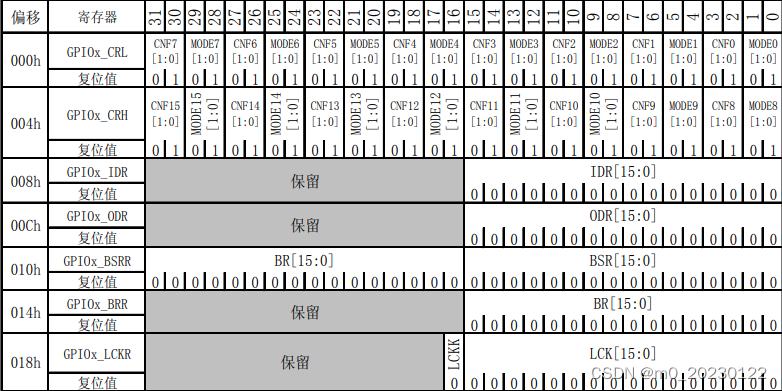
通过GPIO寄存器地址映像图可以发现每个寄存器都是4个字节,上一篇博文我们定义了GPIOB_BASE,它是一个32为的地址,指向的是GPIOB的CRL寄存器,每增加4个字节指向下一个寄存器,这就和C语言的结构体类似。下面我们定义一个GPIO的寄存器的结构体
typedef unsigned int     uint32_t;
typedef unsigned short   uint16_t;

typedef struct
{
	uint32_t CRL;
	uint32_t CRH;
	uint32_t IDR;
	uint32_t ODR;
	uint32_t BSRR;
	uint32_t BRR;
	uint32_t LCKR;
}GPIO_TypeDef;
开头两行代码定义了两个类型别名。第一个类型别名是'uint32_t',它表示无符号整数类型,其大小为32位。第二个类型别名是'uint16_t',它表示无符号短整数类型,其大小为16位。通过使用这两个类型别名,我们可以更方便地声明和使用相应类型的变量。这样有助于提高代码的可读性和可维护性。?试想一下,如果定义的GPIO结构体里面的寄存器地址和原本这些寄存器的地址一致,我们就可以直接通过结构体调用这些寄存器。这里我们就要用到C语言里面的强制类型转换
#define GPIOB ((GPIO_TypeDef*)GPIOB_BASE)2.定义时钟RCC结构体
typedef struct
{
	uint32_t CR;
	uint32_t CFGR;
	uint32_t CIR;
	uint32_t APB2RSTR;
	uint32_t APB1RSTR;
	uint32_t AHBENR;
	uint32_t APB2ENR;
	uint32_t APB1ENR;
	uint32_t BDCR;
	uint32_t CSR;
}RCC_TypeDef;
?经过这些操作后,GPIOB就指向一段内存,这些内存里面就包含了GPIOB所有的寄存器,并且地址一一对应。所以我们就可以通过结构体去调用各个寄存器。同样的道理,时钟RCC也可以用同样的方法。下面是完整代码:
main.c:
#include "stm32f10x.h"

int main()
{
  //打开GPIOB端口的时钟
  RCC->APB2ENR |=((1)<<3);

  //控制I/O口为输出
  GPIOB->CRL &= ~((0x0f)<<(4*0));
  GPIOB->CRL |=((1)<<(4*0));

  //控制ODR寄存器
  GPIOB->ODR &=~(1<<0);  //亮
  //GPIOB_ODR |=(1<<0);    //灭
}
?stm32f10x.h:
//用来存放寄存器映射的代码

#define PERIPH_BASE       ((unsigned int)0x40000000)  //基地址
#define APB1PERIPH_BASE   PERIPH_BASE                 //APB1基地址
#define APB2PERIPH_BASE   (PERIPH_BASE + 0x10000)     //APB2基地址
#define AHBPERIPH_BASE    (PERIPH_BASE + 0x20000)     //AHB基地址

#define RCC_BASE          (AHBPERIPH_BASE + 0x1000)   //RCC基地址
#define GPIOB_BASE        (APB2PERIPH_BASE + 0x0C00)  //GPIOB基地址

#define RCC_APB2ENR        *(unsigned int * )(RCC_BASE + 0x18)

typedef unsigned int     uint32_t;
typedef unsigned short   uint16_t;

typedef struct
{
	uint32_t CRL;
	uint32_t CRH;
	uint32_t IDR;
	uint32_t ODR;
	uint32_t BSRR;
	uint32_t BRR;
	uint32_t LCKR;
}GPIO_TypeDef;

typedef struct
{
	uint32_t CR;
	uint32_t CFGR;
	uint32_t CIR;
	uint32_t APB2RSTR;
	uint32_t APB1RSTR;
	uint32_t AHBENR;
	uint32_t APB2ENR;
	uint32_t APB1ENR;
	uint32_t BDCR;
	uint32_t CSR;
}RCC_TypeDef;

#define GPIOB ((GPIO_TypeDef*)GPIOB_BASE)
#define RCC ((RCC_TypeDef*)RCC_BASE)
二、端口置位复位函数
这一步操作需要在工程中添加两个文件,stm32f10x_gpio.h和stm32f10x_gpio.c。在stm32f10x_gpio.中定义两个函数,一个置位一个复位。置位我们不再操作ODR这个寄存器,我们操作BSRR这个端口位设置/清除寄存器
1.定义置位函数

这里我们使用BSRR的低16位:
void GPIO_SetBit(GPIO_TypeDef *GPIOx,uint16_t GPIO_Pin)
{
	GPIOx->BSRR |= GPIO_Pin;
}
这里我们需要定义16个宏,因为我们要使BSRR寄存器的位0置1,其他位全位0,就是(uint16_t)0x0001,所以共有16种情况:
#define GPIO_Pin_0    ((uint16_t)0x0001)   /*!<选择Pin0 */      //(0000000 0000001)b
#define GPIO_Pin_1    ((uint16_t)0x0002)   /*!<选择Pin1 */      //(0000000 0000001)b
#define GPIO_Pin_2    ((uint16_t)0x0004)   /*!<选择Pin2 */      //(0000000 0000001)b
#define GPIO_Pin_3    ((uint16_t)0x0008)   /*!<选择Pin3 */      //(0000000 0000001)b
#define GPIO_Pin_4    ((uint16_t)0x0010)   /*!<选择Pin4 */      //(0000000 0000001)b
#define GPIO_Pin_5    ((uint16_t)0x0020)   /*!<选择Pin5 */      //(0000000 0000001)b
#define GPIO_Pin_6    ((uint16_t)0x0040)   /*!<选择Pin6 */      //(0000000 0000001)b
#define GPIO_Pin_7    ((uint16_t)0x0080)   /*!<选择Pin7 */      //(0000000 0000001)b

#define GPIO_Pin_8    ((uint16_t)0x0100)   /*!<选择Pin8 */      //(0000000 0000001)b
#define GPIO_Pin_9    ((uint16_t)0x0200)   /*!<选择Pin9 */      //(0000000 0000001)b
#define GPIO_Pin_10   ((uint16_t)0x0400)   /*!<选择Pin10 */     //(0000000 0000001)b
#define GPIO_Pin_11   ((uint16_t)0x0800)   /*!<选择Pin11 */     //(0000000 0000001)b
#define GPIO_Pin_12   ((uint16_t)0x1000)   /*!<选择Pin12 */     //(0000000 0000001)b
#define GPIO_Pin_13   ((uint16_t)0x2000)   /*!<选择Pin13 */     //(0000000 0000001)b
#define GPIO_Pin_14   ((uint16_t)0x3000)   /*!<选择Pin14 */     //(0000000 0000001)b
#define GPIO_Pin_15   ((uint16_t)0x4000)   /*!<选择Pin15 */     //(0000000 0000001)b
#define GPIO_Pin_All  ((uint16_t)0xFFFF)   /*!<选择全部引脚*/   //(0000000 0000001)b
?经过这样的宏定义,GPIO_Pin_0表示第0位位1,GPIO_Pin_1表示第1位为1,以此类推。
2.定义复位函数?
接下来我们用相同的方法去定义清除的函数:
void GPIO_ResetBit(GPIO_TypeDef *GPIOx,uint16_t GPIO_Pin)
{
	GPIOx->BRR |=GPIO_Pin;
}
?这里我们使用的是BRR这个清除寄存器
因为我们点亮PB0这个端口的LED,所以当BRR寄存器第0为为1时清除对应的ODR位为0,这样LED就灭了。下面是完整代码:
stm32f10x_gpio.h:
#ifndef __STM32F10X_GPIO_H
#define __STM32F10X_GPIO_H

#include "stm32f10x.h"

#define GPIO_Pin_0    ((uint16_t)0x0001)   /*!<选择Pin0 */      //(0000000 0000001)b
#define GPIO_Pin_1    ((uint16_t)0x0002)   /*!<选择Pin1 */      //(0000000 0000001)b
#define GPIO_Pin_2    ((uint16_t)0x0004)   /*!<选择Pin2 */      //(0000000 0000001)b
#define GPIO_Pin_3    ((uint16_t)0x0008)   /*!<选择Pin3 */      //(0000000 0000001)b
#define GPIO_Pin_4    ((uint16_t)0x0010)   /*!<选择Pin4 */      //(0000000 0000001)b
#define GPIO_Pin_5    ((uint16_t)0x0020)   /*!<选择Pin5 */      //(0000000 0000001)b
#define GPIO_Pin_6    ((uint16_t)0x0040)   /*!<选择Pin6 */      //(0000000 0000001)b
#define GPIO_Pin_7    ((uint16_t)0x0080)   /*!<选择Pin7 */      //(0000000 0000001)b

#define GPIO_Pin_8    ((uint16_t)0x0100)   /*!<选择Pin8 */      //(0000000 0000001)b
#define GPIO_Pin_9    ((uint16_t)0x0200)   /*!<选择Pin9 */      //(0000000 0000001)b
#define GPIO_Pin_10   ((uint16_t)0x0400)   /*!<选择Pin10 */     //(0000000 0000001)b
#define GPIO_Pin_11   ((uint16_t)0x0800)   /*!<选择Pin11 */     //(0000000 0000001)b
#define GPIO_Pin_12   ((uint16_t)0x1000)   /*!<选择Pin12 */     //(0000000 0000001)b
#define GPIO_Pin_13   ((uint16_t)0x2000)   /*!<选择Pin13 */     //(0000000 0000001)b
#define GPIO_Pin_14   ((uint16_t)0x3000)   /*!<选择Pin14 */     //(0000000 0000001)b
#define GPIO_Pin_15   ((uint16_t)0x4000)   /*!<选择Pin15 */     //(0000000 0000001)b
#define GPIO_Pin_All  ((uint16_t)0xFFFF)   /*!<选择全部引脚*/   //(0000000 0000001)b

void GPIO_SetBit(GPIO_TypeDef *GPIOx,uint16_t GPIO_Pin);
void GPIO_ResetBit(GPIO_TypeDef *GPIOx,uint16_t GPIO_Pin);
#endif
?stm32f10x_gpio.c:
#include "stm32f10x_gpio.h"

void GPIO_SetBit(GPIO_TypeDef *GPIOx,uint16_t GPIO_Pin)
{
	GPIOx->BSRR |= GPIO_Pin;
}

void GPIO_ResetBit(GPIO_TypeDef *GPIOx,uint16_t GPIO_Pin)
{
	GPIOx->BRR |=GPIO_Pin;
}
main.c:?
#include "stm32f10x.h"

int main()
{
  //打开GPIOB端口的时钟
  RCC->APB2ENR |=((1)<<3);

  //控制I/O口为输出
  GPIOB->CRL &= ~((0x0f)<<(4*0));
  GPIOB->CRL |=((1)<<(4*0));

  //控制ODR寄存器
  GPIO_SetBit(GPIOB,GPIO_Pin_0);    //灭

  GPIO_ResetBit(GPIOB,GPIO_Pin_0);  //亮

}
三、编写GPIO相关结构体
下面我们需要对进行升华和完善,将初始化中的二进制或者十六进制的赋值操作进行优化,这样可以提高可读性,读者看到也能快速的理解这些代码的功能。
1.?定义GPIO初始化结构体
如同上面寄存器结构体定义一样,我们可以定义GPIO初始化的结构体。通过本文开头那篇博文的学习我们可以知道点亮LED的步骤为配置GPIO引脚、选择GPIO引脚速率、选择GPIO引脚工作模式。知道点亮LED操作流程,下面我们定义一个GPIO初始化结构体:
typedef struct{
	uint16_t GPIO_Pin;      //选择要配置的GPIO引脚
	uint16_t GPIO_Speed;    //选择GPIO引脚速率
	uint16_t GPIO_Mode;     //选择GPIO引脚工作模式
}GPIO_InitTypeDef;
这里我们将结构体里面的变量设置为16位,为了编程的时候不犯错,我们可以限定结构体里面的成员只能取某些值。在C语言里面枚举定义可以实现这个功能。由于GPIO引脚我们上面已经定义了,这里我们还需要定义两个枚举定义的结构体用来限制引脚速率和引脚工作模式。
2.定义速度和模式的枚举结构体?
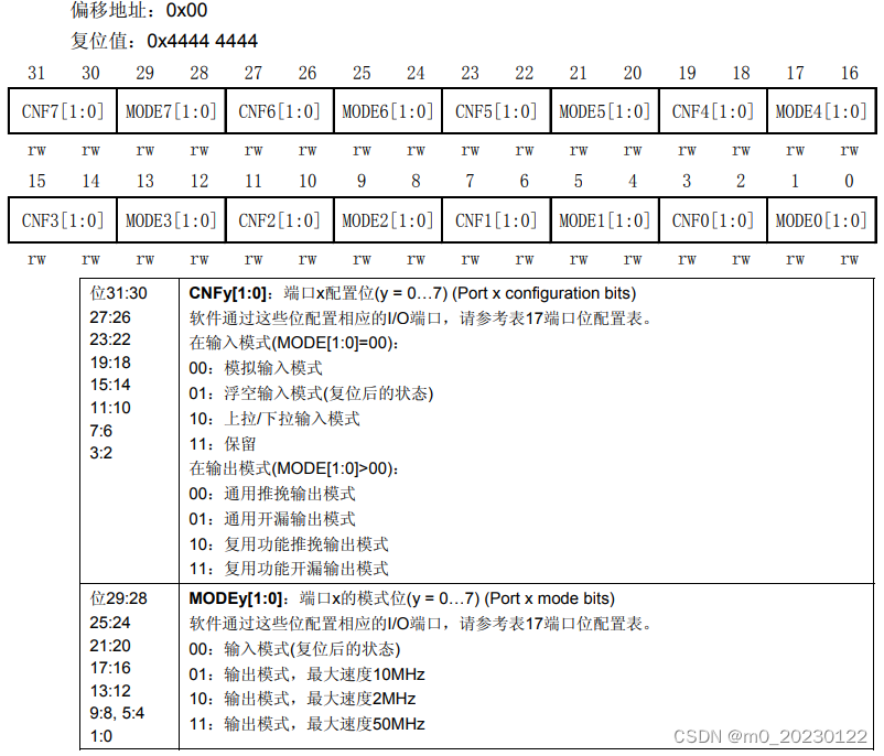
?通过上图可以发现输入输出模式有八种,速度有三种。
速度枚举结构体:
typedef enum
{
	GPIO_Speed_10MHZ = 1,
	GPIO_Speed_2MHZ,
	GPIO_Speed_50MHZ
}GPIOSpeed_TypeDef;
这里只有10MHZ赋值位1,后面不用赋值,因为定义enum它会自动默认后面的变量加1,这样就对应10MHZ是01,2MHZ是10也就是2,50MHZ是11也就是3。

通过这个图可以知道位0和位1都是0,然后位2和位3对应上图的两位二进制,位4用来区分输入和输出,位5和位6用来表示上拉和下拉。?通过上表可以知道每个模式的十六进制的值,于是可以定义输入输出模式的枚举结构体:
typedef enum
{
	GPIO_Mode_AIN = 0x0,
	GPIO_Mode_IN_FLOATING = 0x04,
	GPIO_Mode_IPD = 0x28,
	GPIO_Mode_IPU = 0x48,

	GPIO_Mode_Out_0D = 0x14,
	GPIO_Mode_Out_PP = 0x10,
	GPIO_Mode_AF_OD = 0x1C,
	GPIO_Mode_AF_PP = 0x18,
}GPIOMode_TypeDef;
完成上面两步,那我们怎么把这些值写进寄存器里面呢?这里就需要用到一个初始化函数void GPIO_Init(GPIO_TypeDef* GPIOx, GPIO_InitTypeDef* GPIO_InitStruct),在这个函数里面有两个形参,第一个以结构体指针的形式传进来,表示我们使用的是哪一个外设,第二个是定义的初始化结构体的地址。这里直接将这个函数从官方固件库中拷贝到stm32f10x_gpio.里面。接着在main.c中使用初始化函数来配置GPIO引脚去点亮LED:
#include "stm32f10x.h"
#include "stm32f10x_gpio.h"

int main()
{
  GPIO_InitTypeDef GPIO_InitStructure;

  //打开GPIOB端口的时钟
  RCC->APB2ENR |= (1<<3);

  GPIO_InitStructure.GPIO_Pin = GPIO_Pin_0;          //PB0
  GPIO_InitStructure.GPIO_Mode = GPIO_Mode_Out_PP;   //推挽输出
  GPIO_InitStructure.GPIO_Speed = GPIO_Speed_10MHZ;  //速度10MHZ
  GPIO_Init(GPIOB, &GPIO_InitStructure);             //初始化

  GPIO_SetBit(GPIOB,GPIO_Pin_0);

  GPIO_ResetBit(GPIOB,GPIO_Pin_0);

}
四、小结?
通过上面的学习,我们自己编写了自己的简单的固件库,这不仅能帮助我们正确使用固件库,还能促进我们更深入地理解底层原理,从而提升我们的技术水平。
本文来自互联网用户投稿,该文观点仅代表作者本人,不代表本站立场。本站仅提供信息存储空间服务,不拥有所有权,不承担相关法律责任。 如若内容造成侵权/违法违规/事实不符,请联系我的编程经验分享网邮箱:chenni525@qq.com进行投诉反馈,一经查实,立即删除!
- Python教程
- 深入理解 MySQL 中的 HAVING 关键字和聚合函数
- Qt之QChar编码(1)
- MyBatis入门基础篇
- 用Python脚本实现FFmpeg批量转换
- priority_queue比较规则
- 2024年程序员必备:掌握未来技术架构的关键方向
- 亚马逊云科技:向量数据存储在生成式人工智能应用程序中的作用
- 数据结构栈实现(赋完整代码)
- KVM配置桥接
- 【UE Niagara学习笔记】07 - 火焰的热变形效果
- 《Linux系统与网络管理》复习题库---shell编程题
- 【.NET Core】匿名方法与扩展方法
- 有挑战才有收获!PaddleOCR算法模型挑战赛火热开启!
- 使用 xshell 登陆云服务器