Analog-to-digital converter (ADC)
Overview
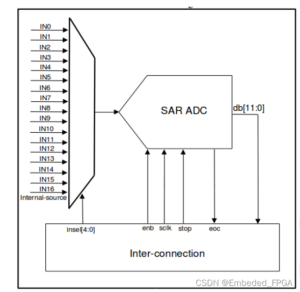
3×12-bit, 1.0 MSPS A/D converters are embedded and each ADC has up to 17 multiplexed channels allowing it measure signals from sixteen external and one internal sources,and 3 MSPS in triple interleaved mode
A/D conversion of the various channels can be performed in single, continuous, scan or discontinuous mode.
The analog watchdog feature allows the application to detect if the input voltage goes outside the user-defined high or low thresholds.
The ADC input clock is generated from the inter-connection logic clock.
Characteristics
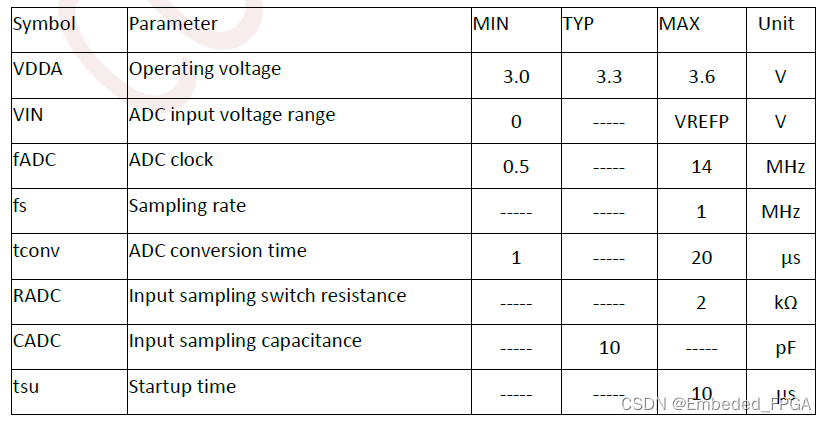
(1) ADC sampling rate: 1 MSPS for 12-bit resolution
(2) Programmable sampling time
(3) 16 external analog inputs and 1 channel for internal temperature sensor or for VBAT
(4) Converts a single channel or scans a sequence of channels
(5) Single mode converts selected inputs once per trigger
(6) Continuous mode converts selected inputs continuously
(7) Discontinuous mode
(8) Analog watchdog
(9) ADC supply requirements: 3.0V to 3.6V, and typical power supply voltage is 3.3V
(10) ADC input range: VSSA ≤VIN ≤VREFP
Pins and internal signals
ADC internal signals

ADC pins definition

Temperature sensor
The temperature sensor can be used to measure the ambient temperature of the device. The sensor output voltage can be converted into a digital value by ADC. The sampling time for the temperature sensor is recommended to be set to at least 10μs.
The output voltage of the temperature sensor changes linearly with temperature. Because there is an offset, varies from chip to chip due to process variation, the internal temperature sensor is more suited for applications that detect temperature variations instead of absolute temperature.
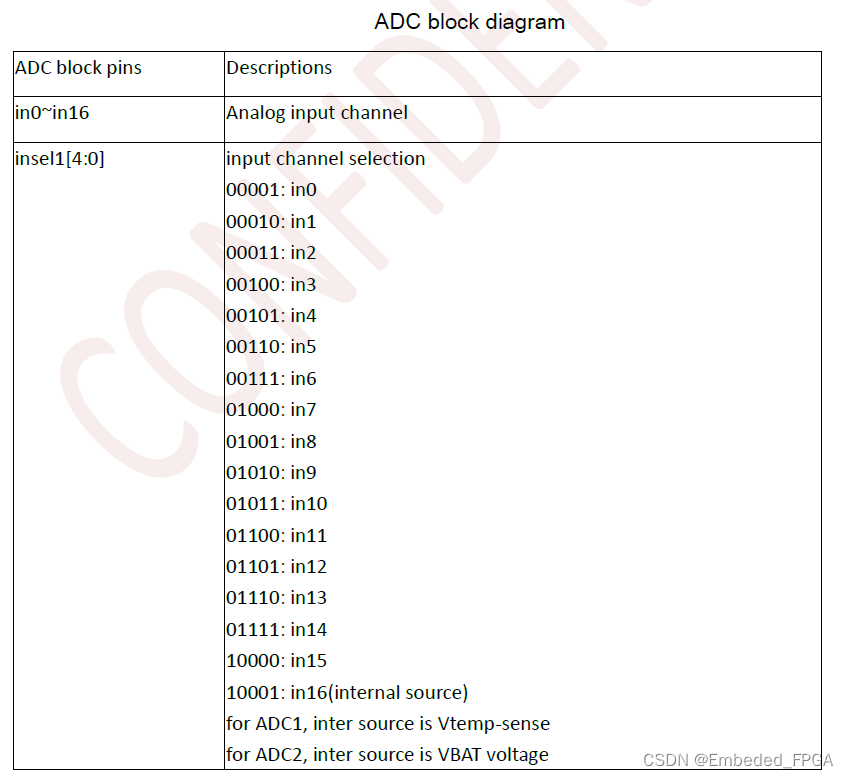
ADC block pins

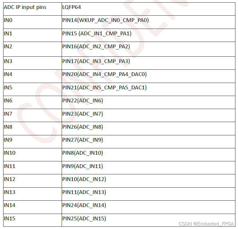
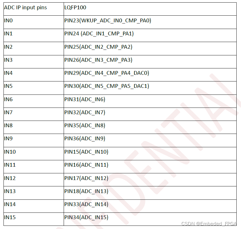
ADC input signals vs package pins
ADC characteristics
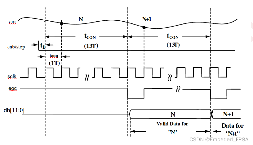
ADC timing diagram
After the start of ADC conversion and after 13 clock cycles, the EOC flag is set and the 12-bit Data is ready.

本文来自互联网用户投稿,该文观点仅代表作者本人,不代表本站立场。本站仅提供信息存储空间服务,不拥有所有权,不承担相关法律责任。 如若内容造成侵权/违法违规/事实不符,请联系我的编程经验分享网邮箱:chenni525@qq.com进行投诉反馈,一经查实,立即删除!
- Python教程
- 深入理解 MySQL 中的 HAVING 关键字和聚合函数
- Qt之QChar编码(1)
- MyBatis入门基础篇
- 用Python脚本实现FFmpeg批量转换
- Arbitrum之后,估值18亿美元Scroll又火了
- 鸿蒙Harmony(四)ArkUI---基础组件:Image
- Python武器库开发-武器库篇之密码生成器开发(四十九)
- 数据结构OJ实验6-二叉树的遍历以及应用
- 数据分析工具PlotJuggler使用小技巧
- Gin之gin介绍和安装
- 【Linux】常用的基本命令指令①
- 【动态规划---dp经典问题总结:】
- 微信小程序封装vant 下拉框select 多选组件
- 【模型部署入门 一】:Pytorch图像分类模型转换ImageNet1000类预训练模型转ONNX